Difference between revisions of "Main Page"
| Line 29: | Line 29: | ||
<slideshow sequence="random" transition="fade" refresh="10000"> | <slideshow sequence="random" transition="fade" refresh="10000"> | ||
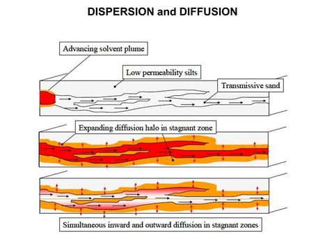
| − | [[File:WH Picture1. | + | [[File:WH Picture1.JPG|thumb|center|x350px|link=Dispersion and Diffusion|Molecular diffusion slowly transports solutes into clay-rich, lower permeability zones]] |
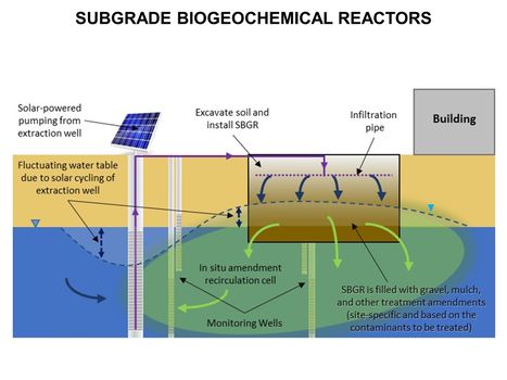
| − | [[File:WH Picture2. | + | [[File:WH Picture2.JPG|thumb|center|x350px|link=Subgrade Biogeochemical Reactor (SBGR)|Typical subgrade biogeochemical reactor (SBGR) layout. The SBGR is an in situ remediation technology for treatment of contaminated source areas and groundwater plume hot spots<br/>]] |
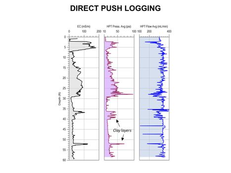
| − | [[File:WH Picture3. | + | [[File:WH Picture3.JPG|thumb|center|x350px|link=Direct Push Logging|An Hydraulic Profiling Tool (HPT) log with electrical conductivity (EC) on left, injection pressure in middle, and flow rate on the right]] |
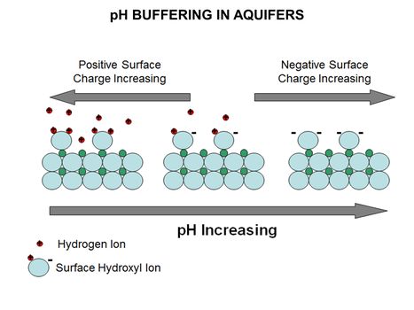
| − | [[File:WH Picture4. | + | [[File:WH Picture4.JPG|thumb|center|x350px|link=PH Buffering in Aquifers|Diagram of mineral surface exchanging hydrogen ions with varying pH. The surface of most aquifer minerals carries an electrical charge that varies with pH]] |
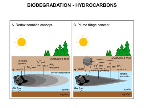
| − | [[File:WH Picture5. | + | [[File:WH Picture5.JPG|thumb|center|x350px|link=Biodegradation - Hydrocarbons|Comparison of the longitudinal redox zonation concept (A) and the plume fringe concept (B). Both concepts describe the spatial distribution of electron acceptors and respiration processes in a hydrocarbon contaminant plume]] |
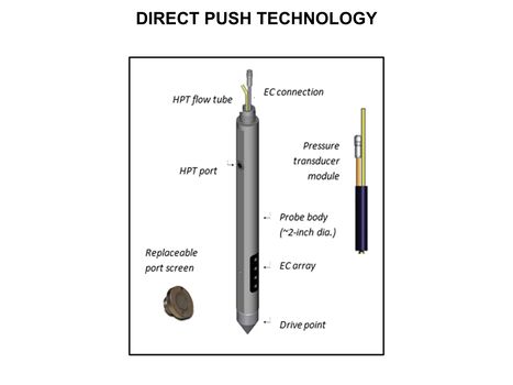
| − | [[File:WH Picture6. | + | [[File:WH Picture6.JPG|thumb|center|x350px|link=Direct Push Logging|Schematic of an Hydraulic Profiling Tool (HPT) probe. HPT were developed to better understand formation permeability and the distribution of permeable and low permeability zones in unconsolidated formations]] |
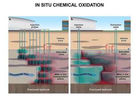
| − | [[File:WH Picture7. | + | [[File:WH Picture7.JPG|thumb|center|x350px|link=Chemical Oxidation Design Considerations(In Situ - ISCO)|In situ chemical oxidation using (a) direct-push injection probes or (b) well-to-well flushing to delivery oxidants (shown in blue) into a target treatment zone of groundwater contaminated by dense nonaqueous phase liquid compounds (shown in red)]] |
| − | [[File:WH Picture8. | + | [[File:WH Picture8.JPG|thumb|center|x350px|link=Geophysical Methods - Case_Studies|High-resolution 3D cross-borehole electrical imaging of contaminated fractured rock at the former Naval Air Warfare Center in New Jersey. Cross-borehole resistivity tomography imaging is a geophysical technique that can be used for site characterization and monitoring by observing variations in the electrical properties of subsurface materials]] |
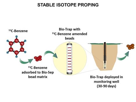
| − | [[File:WH Picture9. | + | [[File:WH Picture9.JPG|thumb|center|x350px|link=Stable_Isotope_Probing_(SIP)|Stable isotope probing (SIP) in use: Loading, deployment and recovery of Bio-Trap® passive sampler with 13C-labeled benzene. Stable isotope probing (SIP) is used to conclusively determine whether in situ biodegradation of a contaminant is occurring]] |
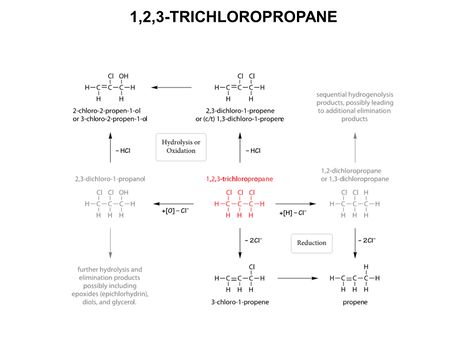
| − | [[File:WH Picture10. | + | [[File:WH Picture10.JPG|thumb|center|x350px|link=1,2,3-Trichloropropane|Summary of anticipated, primary reaction pathways for degradation of 1,2,3-Trichloropropane (TCP). TCP is a man-made chemical that was used in the past primarily as a solvent and extractive agent, a paint and varnish remover, and as a cleaning and degreasing agent]] |
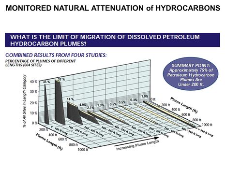
| − | [[File:WH Picture11. | + | [[File:WH Picture11.JPG|thumb|center|x350px|link=Monitored Natural Attenuation (MNA) of Fuels|Distribution of BTEX plume lengths from 604 hydrocarbon sites. Monitored Natural Attenuation (MNA) is one of the most commonly used remediation approaches for groundwater contaminated with petroleum hydrocarbons (PHCs) and certain fuel additives such as fuel oxygenates or lead scavengers]] |
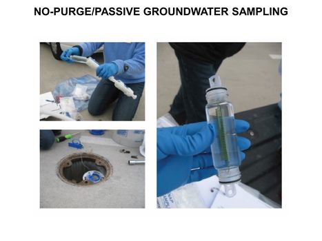
| − | [[File:WH Picture12. | + | [[File:WH Picture12.JPG|thumb|center|x350px|link=Groundwater Sampling - No-Purge/Passive|No-purge and passive sampling methods eliminate the pre-purging step for groundwater sample collection and represent alternatives to conventional sampling methods that rely on low-flow purging of a well prior to collection. The Snap SamplerTM is an example of a passive grab sampler]] |
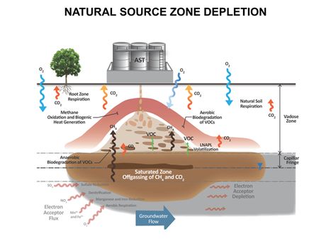
| − | [[File:WH Picture13. | + | [[File:WH Picture13.JPG|thumb|center|x350px|link=Natural Source Zone Depletion (NSZD)|Conceptualization of Vapor Transport-related Natural Source Zone Depletion (NSZD) processes at a Petroleum Release Site]] |
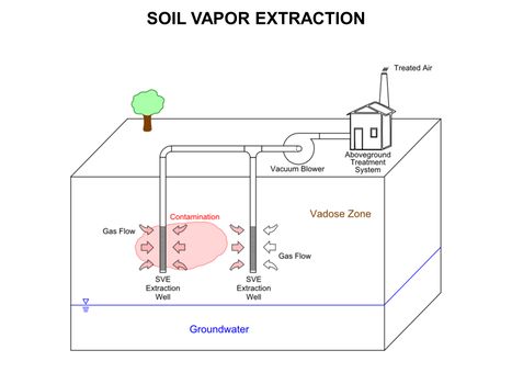
| − | [[File:WH Picture14. | + | [[File:WH Picture14.JPG|thumb|center|x350px|link=Soil Vapor Extraction (SVE)|Conceptual diagram of basic Soil Vapor Extraction (SVE) system for vadose zone remediation. (SVE) is a common and typically effective physical treatment process for remediation of volatile contaminants in vadose zone (unsaturated) soils]] |
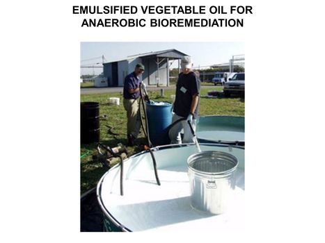
| − | [[File:WH Picture15. | + | [[File:WH Picture15.JPG|thumb|center|x350px|link=Emulsified Vegetable Oil (EVO) for Anaerobic Bioremediation|Emulsified Vegetable Oil (EVO) mixed in field during early pilot test. EVO is commonly added as a slowly fermentable substrate to stimulate the in situ anaerobic bioremediation of chlorinated solvents, explosives, perchlorate, chromate, and other contaminants]] |
| − | [[File:WH Picture16. | + | [[File:WH Picture16.JPG|thumb|center|x350px|link=Vapor_Intrusion_(VI)|Key elements of vapor intrusion pathways]] |
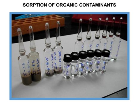
| − | [[File:WH Picture17. | + | [[File:WH Picture17.JPG|thumb|center|x350px|link=Sorption_of_Organic_Contaminants|Batch reactor experiments to generate points on a sorption isotherm]] |
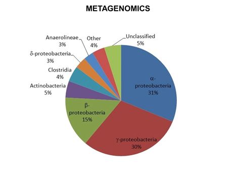
| − | [[File:WH Picture18. | + | [[File:WH Picture18.JPG|thumb|center|x350px|link=Metagenomics|Results for metagenomic analysis of a groundwater sample obtained from a site impacted with petroleum hydrocarbons]] |
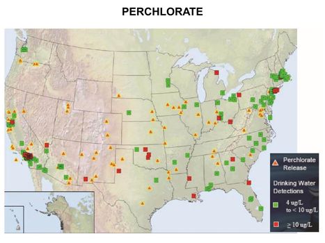
| − | [[File:WH Picture19. | + | [[File:WH Picture19.JPG|thumb|center|x350px|link=Perchlorate|Perchlorate releases and drinking water detections]] |
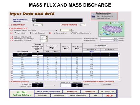
| − | [[File:WH Picture20. | + | [[File:WH Picture20.JPG|thumb|center|x350px|link=Mass_Flux_and_Mass_Discharge|Data input screen for ESTCP Mass Flux Toolkit]] |
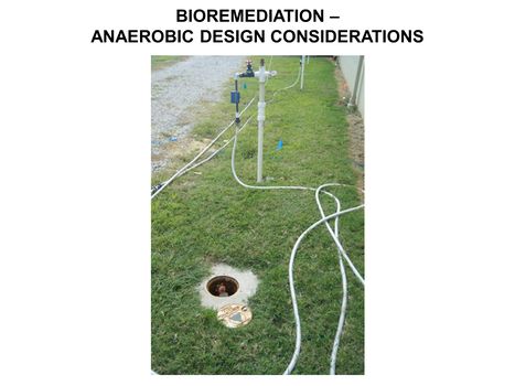
| − | [[File:WH Picture21. | + | [[File:WH Picture21.JPG|thumb|center|x350px|link=Bioremediation_-_Anaerobic_Design_Considerations|Amendment addition for biobarrier]] |
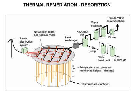
| − | [[File:WH Picture22. | + | [[File:WH Picture22.JPG|thumb|center|x350px|link=Thermal_Remediation_-_Desorption|Thermal Remediation - Desorption schematic]] |
</slideshow> | </slideshow> | ||
Revision as of 15:15, 13 May 2019
Peer Reviewed. Accessible. Written By Experts |
 |
| The goal of the ENVIRO.wiki is to make scientific and engineering research results more accessible to the target audience, facilitating the permitting, design and implementation of environmental projects. Articles are written and edited by invited experts (see Contributors) to summarize current knowledge for environmental professionals on an array of topics, with cross-linked references to reports and technical literature. | See Table of Contents Your Environmental Information Gateway |
Featured article / Biodegradation - Hydrocarbons (Full article...) |
Enviro Wiki Highlights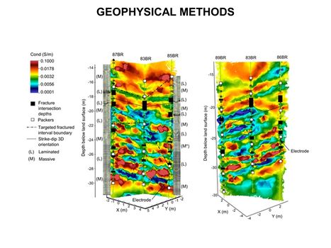 High-resolution 3D cross-borehole electrical imaging of contaminated fractured rock at the former Naval Air Warfare Center in New Jersey. Cross-borehole resistivity tomography imaging is a geophysical technique that can be used for site characterization and monitoring by observing variations in the electrical properties of subsurface materials |
