|
|
| (554 intermediate revisions by the same user not shown) |
| Line 1: |
Line 1: |
| − | ==OPTically-based In-situ Characterization System (OPTICS)== | + | ==Estimating PCE/TCE Abiotic First-Order Reductive Dechlorination Rate Constants in Clayey Soils Under Anoxic Conditions== |
| − | OPTICS combines robust aquatic instrumentation and innovative data processing techniques to measure concentrations of a wide range of dissolved and particulate chemical contaminants in surface water at unprecedented scales. OPTICS is used for a variety of environmental applications including remedial investigation, conceptual site model validation, baseline characterization, source control evaluation, plume characterization, and remedial monitoring.
| + | The U.S. Department of Defense (DoD) faces many challenges in restoring aquifers at contaminated sites, often due to back-diffusion of tetrachloroethene (PCE) and trichloroethene (TCE) from low-permeability clay zones. The uptake, storage, and subsequent long-term release of these dissolved contaminants from clays are key processes in understanding the longevity, intensity, and risks associated with many persistent chlorinated ethene groundwater plumes. Although naturally occurring abiotic and biotic dechlorination processes in clays may reduce stored contaminant mass and significantly aid natural attenuation, no standardized field method currently exists to verify or quantify these reactions. It is critical to remediation design efforts to demonstrate and validate a cost-effective in situ approach for assessing these dechlorination processes using first-order rate constants. An approach was developed and applied across eight DoD sites to support Remedial Project Managers (RPMs) and regulators in evaluating natural attenuation potential in clay-rich environments. |
| − | | |
| | <div style="float:right;margin:0 0 2em 2em;">__TOC__</div> | | <div style="float:right;margin:0 0 2em 2em;">__TOC__</div> |
| | | | |
| | '''Related Article(s):''' | | '''Related Article(s):''' |
| | | | |
| − | *[[Contaminated Sediments - Introduction]] | + | *[[Monitored Natural Attenuation (MNA)]] |
| − | *[[Characterization, Assessment & Monitoring]] | + | *[[Monitored Natural Attenuation (MNA) of Chlorinated Solvents]] |
| − | *[[Mercury in Sediments]] | + | *[[Monitored Natural Attenuation - Transitioning from Active Remedies]] |
| | + | *[[Matrix Diffusion]] |
| | + | *[[REMChlor - MD]] |
| | | | |
| − | '''Contributor(s):''' | + | '''Contributors:''' Dani Tran, Dr. Charles Schaefer, Dr. Charles Werth |
| | | | |
| − | *Grace Chang, Ph.D. | + | '''Key Resource:''' |
| − | *Todd Martin, P.E.
| + | *Schaefer, C.E, Tran, D., Nguyen, D., Latta, D.E., Werth, C.J., 2025. Evaluating Mineral and In Situ Indicators of Abiotic Dechlorination in Clayey Soils<ref name="SchaeferEtAl2025"/> |
| | | | |
| − | '''Key Resource(s):'''
| + | ==Introduction== |
| − | | + | Cost-effective methods are needed to verify the occurrence of natural dechlorination processes and quantify their dechlorination rates in clays under ambient in situ conditions in order to reliably predict their long-term influence on plume longevity and mass discharge. However, accurately determining these rates is challenging due to slow reaction kinetics, the transient nature of transformation products, and the interplay of biotic and abiotic mechanisms within the clay matrix or at clay-sand interfaces. Tools capable of quantifying these reactions and assessing their role in mitigating plume persistence would be a significant aid for long-term site management. |
| − | *Optically based quantification of fluxes of mercury, methyl mercury, and polychlorinated biphenyls (PCBs) at Berry’s Creek tidal estuary, New Jersey<ref name="ChangEtAl2019">Chang, G., Martin, T., Whitehead, K., Jones, C., Spada, F., 2019. Optically based quantification of fluxes of mercury, methyl mercury, and polychlorinated biphenyls (PCBs) at Berry’s Creek tidal estuary, New Jersey. Limnology and Oceanography, 64(1), pp. 93-108. [https://doi.org/10.1002/lno.11021 doi: 10.1002/lno.11021] [[Media: ChangEtAl2019.pdf | Open Access Article]]</ref>
| |
| − | | |
| − | *OPTically-based In-situ Characterization System (OPTICS) to quantify concentrations of mass fluxes of mercury and methylmercury in South River, Virginia, USA<ref name="ChangEtAl2018">Chang, G., Martin, T., Spada, F., Sackmann, B., Jones, C., Whitehead, K., 2018. OPTically-based In-situ Characterization System (OPTICS) to quantify concentrations and mass fluxes of mercury and methylmercury in South River, Virginia, USA. River Research and Applications, 34(9), pp. 1132-1141. [https://doi.org/10.1002/rra.3361 doi: 10.1002/rra.3361]</ref>
| |
| | | | |
| − | *Evaluation of stormwater as a potential source of polychlorinated biphenyls (PCBs) to Pearl Harbor, Hawaii<ref name="ChangEtAl2024">Chang, G., Spada, F., Brodock, K., Hutchings, C., Markillie, K., 2024. Evaluation of stormwater as a potential source of polychlorinated biphenyls (PCBs) to Pearl Harbor, Hawaii. Case Studies in Chemical and Environmental Engineering, 9, Article 100659. [https://doi.org/10.1016/j.cscee.2024.100659 doi: 10.1016/j.cscee.2024.100659] [[Media: ChangEtAl2024.pdf | Open Access Article]]</ref>
| + | For reductive abiotic dechlorination under anoxic conditions, a 1% hydrochloric acid (HCl) extraction of a sample of native clay coupled with X-ray diffraction (XRD) data can be used as a screening level tool to estimate reductive dechlorination rate constants. These rate constants can be inserted into fate and transport models such as [[REMChlor - MD]]<ref>Falta, R., and Wang, W., 2017. A semi-analytical method for simulating matrix diffusion in numerical transport models. Journal of Contaminant Hydrology, 197, pp. 39-49. [https://doi.org/10.1016/j.jconhyd.2016.12.007 doi: 10.1016/j.jconhyd.2016.12.007] [[Media: FaltaWang2017.pdf | Open Access Manuscript]]</ref><ref>Kulkarni, P.R., Adamson, D.T., Popovic, J., Newell, C.J., 2022. Modeling a well-charactized perfluorooctane sulfate (PFOS) source and plume using the REMChlor-MD model to account for matrix diffusion. Journal of Contaminant Hydrology, 247, Article 103986. [https://doi.org/10.1016/j.jconhyd.2022.103986 doi: 10.1016/j.jconhyd.2022.103986] [[Media: KulkarniEtAl2022.pdf | Open Access Manuscript]]</ref> to quantify abiotic dechlorination impacts within clay aquitards on chlorinated solvent plumes. Thus, determination of the abiotic reductive dechlorination rate constant for a particular clayey soil can be readily utilized to provide a more accurate assessment of aquifer cleanup timeframes for groundwater plumes that are being sustained by contaminant back-diffusion. |
| − | | |
| − | ==Introduction==
| |
| − | [[File:StrathmannFig1.png | thumb |300px|Figure 1. Illustration of PFAS adsorption by anion exchange resins (AERs). Incorporation of longer alkyl group side chains on the cationic quaternary amine functional groups leads to PFAS-resin hydrophobic interactions that increase resin selectivity for PFAS over inorganic anions like Cl<sup>-</sup>.]]
| |
| | | | |
| − | [[File:StrathmannFig2.png | thumb | 300px| Figure 2. Effect of perfluoroalkyl carbon chain length on the estimated bed volumes (BVs) to 50% breakthrough of PFCAs and PFSAs observed in a pilot study<ref name="StrathmannEtAl2020">Strathmann, T.J., Higgins, C., Deeb, R., 2020. Hydrothermal Technologies for On-Site Destruction of Site Investigation Wastes Impacted by PFAS, Final Report - Phase I. SERDP Project ER18-1501. [https://serdp-estcp.mil/projects/details/b34d6396-6b6d-44d0-a89e-6b22522e6e9c Project Website] [[Media: ER18-1501.pdf| Report.pdf]]</ref> treating PFAS-contaminated groundwater with the PFAS-selective AER (Purolite PFA694E) ]] | + | ==Recommended Approach== |
| | + | [[File: TranFig1.png | thumb | 500 px | Figure 1: First-order rate constants for abiotic reductive dechlorination of TCE under anaerobic conditions. Circles are data from Schaefer ''et al.'', 2021<ref>Schaefer, C.E., Ho, P., Berns, E., Werth, C., 2021. Abiotic dechlorination in the presence of ferrous minerals. Journal of Contaminant Hydrology, 241, 103839. [https://doi.org/10.1016/j.jconhyd.2021.103839 doi: 10.1016/j.jconhyd.2021.103839] [[Media: SchaeferEtAl2021.pdf | Open Access Manuscript]]</ref>, filled squares from Schaefer ''et al.'', 2018<ref name="SchaeferEtAl2018"/>, and Schaefer ''et al.'', 2017<ref>Schaefer, C.E., Ho., Gurr, C., Berns, E., Werth, C., 2017. Abiotic dechlorination of chlorinated ethenes in natural clayey soils: impacts of mineralogy and temperature. Journal of Contaminant Hydrology, 206, pp. 10-17. [https://doi.org/10.1016/j.jconhyd.2017.09.007 doi: 10.1016/j.jconhyd.2017.09.007] [[Media: SchaeferEtAl2017.pdf | Open Access Manuscript]]</ref>, and open squares from Schaefer ''et al.'', 2025<ref name="SchaeferEtAl2025"/>. ]] |
| | + | [[File: TranFig2.png | thumb | 600 px | Figure 2: Flowchart diagram of field screening procedures]] |
| | + | The recommended approach builds upon the methodology and findings of a recent study<ref name="SchaeferEtAl2025">Schaefer, C.E., Tran, D., Nguyen, D., Latta, D.E., Werth, C.J., 2025. Evaluating Mineral and In Situ Indicators of Abiotic Dechlorination in Clayey Soils. Groundwater Monitoring and Remediation, 45(2), pp. 31-39. [https://doi.org/10.1111/gwmr.12709 doi: 10.1111/gwmr.12709]</ref>, emphasizing field-based and analytical techniques to quantify abiotic first-order reductive dechlorination rate constants for PCE and TCE in clayey soils under anoxic conditions. Key components of this evaluation are listed below: |
| | + | #<u>Zone Identification:</u> The focus of the investigation should be to delineate clayey zones adjacent to hydraulically conductive zones. |
| | + | #<u>Ferrous Mineral Quantification:</u> Assess ferrous mineral context in clay via 1% HCl extraction at ambient temperature over a 10-minute interval. |
| | + | #<u>Mineralogical Characterization:</u> Conduct XRD analysis with the specific intent of identifying the presence of pyrite and biotite. |
| | + | #<u>Reduced Gas Analysis:</u> Measurement of reduced gases such as acetylene, ethene, and ethane concentrations in clay samples. Gas-tight sampling devices (e.g., En Core® soil samplers by En Novative Technologies, Inc.) should be used to ensure sample integrity during collection and transport. |
| | | | |
| − | Anion exchange is an adsorptive treatment technology that uses polymeric resin beads (0.5–1 mm diameter) that incorporate cationic adsorption sites to remove anionic pollutants from water<ref>SenGupta, A.K., 2017. Ion Exchange in Environmental Processes: Fundamentals, Applications and Sustainable Technology. Wiley. ISBN:9781119157397 [https://onlinelibrary.wiley.com/doi/book/10.1002/9781119421252 Wiley Online Library]</ref>. Anions (e.g., NO<sub>3</sub><sup>-</sup>) are adsorbed by an ion exchange reaction with anions that are initially bound to the adsorption sites (e.g., Cl<sup>-</sup>) during resin preparation. Many per- and polyfluoroalkyl substances (PFAS) of concern, including [[Wikipedia: Perfluorooctanoic acid | perfluorooctanoic acid (PFOA)]] and [[Wikipedia: Perfluorooctanesulfonic acid | perfluorooctane sulfonate (PFOS)]], are present in contaminated water as anionic species that can be adsorbed by anion exchange reactions<ref name="BoyerEtAl2021a" /><ref name="DixitEtAl2021">Dixit, F., Dutta, R., Barbeau, B., Berube, P., Mohseni, M., 2021. PFAS Removal by Ion Exchange Resins: A Review. Chemosphere, 272, Article 129777. [https://doi.org/10.1016/j.chemosphere.2021.129777 doi: 10.1016/j.chemosphere.2021.129777]</ref><ref name="RahmanEtAl2014">Rahman, M.F., Peldszus, S., Anderson, W.B., 2014. Behaviour and Fate of Perfluoroalkyl and Polyfluoroalkyl Substances (PFASs) in Drinking Water Treatment: A Review. Water Research, 50, pp. 318–340. [https://doi.org/10.1016/j.watres.2013.10.045 doi: 10.1016/j.watres.2013.10.045]</ref>.
| + | Clay samples should be collected within a few centimeters of the high-permeability interface, with optional additional sampling further inward. For mineralogical analysis, a defined interval may be collected and subsequently subsampled. To preserve sample integrity, exposure to air should be minimized during collection, transport, and handling. Homogenization should occur within an anaerobic chamber, and if subsamples are required for external analysis, they must be shipped in gas-tight, anaerobic containers. |
| − | <br>
| |
| − | <center><big>Anion Exchange Reaction: '''PFAS<sup>-</sup>'''</big>'''<sub>(aq)</sub><big> + Cl<sup>-</sup></big><sub>(resin bound)</sub><big> ⇒ PFAS<sup>-</sup></big><sub>(resin bound)</sub><big> + Cl<sup>-</sup></big><sub>(aq)</sub>'''</center>
| |
| − | Resins most commonly applied for PFAS treatment are strong base anion exchange resins (SB-AERs) that incorporate [[Wikipedia: Quaternary ammonium cation | quaternary ammonium]] cationic functional groups with hydrocarbon side chains (R-groups) that promote PFAS adsorption by a combination of electrostatic and hydrophobic mechanisms (Figure 1)<ref name="BoyerEtAl2021a" /><ref>Fuller, Mark. Ex Situ Treatment of PFAS-Impacted Groundwater Using Ion Exchange with Regeneration; ER18-1027. [https://serdp-estcp.mil/projects/details/af660326-56e0-4d3c-b80a-1d8a2d613724 Project Website].</ref>. SB-AERs maintain cationic functional groups independent of water pH. Recently introduced ‘PFAS-selective’ AERs show >1,000,000-fold greater selectivity for some PFAS over the Cl<sup>-</sup> initially loaded onto resins<ref name="FangEtAl2021">Fang, Y., Ellis, A., Choi, Y.J., Boyer, T.H., Higgins, C.P., Schaefer, C.E., Strathmann, T.J., 2021. Removal of Per- and Polyfluoroalkyl Substances (PFASs) in Aqueous Film-Forming Foam (AFFF) Using Ion-Exchange and Nonionic Resins. Environmental Science and Technology, 55(8), pp. 5001–5011. [https://doi.org/10.1021/acs.est.1c00769 doi: 10.1021/acs.est.1c00769]</ref>. These resins also show much higher adsorption capacities for PFAS (mg PFAS adsorbed per gram of adsorbent media) than granular activated carbon (GAC) adsorbents.
| |
| | | | |
| − | PFAS of concern have a wide range of structures, including [[Wikipedia: Perfluoroalkyl carboxylic acids | perfluoroalkyl carboxylic acids (PFCAs)]] and [[Wikipedia: Perfluorosulfonic acids | perfluoroalkyl sulfonic acids (PFSAs)]] of varying carbon chain length<ref>Interstate Technology Regulatory Council (ITRC), 2023. Technical Resources for Addressing Environmental Releases of Per- and Polyfluoroalkyl Substances (PFAS). [https://pfas-1.itrcweb.org/ ITRC PFAS Website]</ref>. As such, affinity for adsorption to AERs is heavily dependent upon PFAS structure<ref name="BoyerEtAl2021a" /><ref name="DixitEtAl2021" />. In general, it has been found that the extent of adsorption increases with increasing chain length, and that PFSAs adsorb more strongly than PFCAs of similar chain length (Figure 2)<ref name="FangEtAl2021" /><ref>Gagliano, E., Sgroi, M., Falciglia, P.P., Vagliasindi, F.G.A., Roccaro, P., 2020. Removal of Poly- and Perfluoroalkyl Substances (PFAS) from Water by Adsorption: Role of PFAS Chain Length, Effect of Organic Matter and Challenges in Adsorbent Regeneration. Water Research, 171, Article 115381. [https://doi.org/10.1016/j.watres.2019.115381 doi: 10.1016/j.watres.2019.115381]</ref>. The chain length-dependence supports the conclusion that PFAS-resin hydrophobic mechanisms contribute to adsorption. Adsorption of polyfluorinated structures also depends on structure and prevailing charge, with adsorption of zwitterionic species (containing both anionic and cationic groups in the same structure) to AERs being documented despite having a net neutral charge<ref name="FangEtAl2021" />.
| + | Estimation of the abiotic reductive first-order rate constant for PCE and TCE is based on the “reactive” ferrous content in the clay. Reactive ferrous content (Fe(II)<sub>r</sub>) is estimated as shown in Equation 1: |
| | | | |
| − | ==Reactors for Treatment of PFAS-Contaminated Water==
| + | ::'''Equation 1:''' <big>''Fe(II)<sub><small>r</small></sub> = DA + XRD<sub><small>pyr</small></sub> - XRD<sub><small>biotite</small></sub>''</big> |
| − | [[File:StrathmannFig3.png | thumb | 300px| Figure 3. Fixed bed reactor vessels containing anion exchange resins treating PFAS-contaminated water in the City of Orange, NJ. Water flow goes through both vessels in a lead-lag configuration. Picture credit: AqueoUS Vets.]]
| |
| − | Anion exchange treatment of water is accomplished by pumping contaminated water through fixed bed reactors filled with AERs (Figure 3). A common configuration involves flowing water through two reactors arranged in a lead-lag configuration<ref name="WoodardEtAl2017">Woodard, S., Berry, J., Newman, B., 2017. Ion Exchange Resin for PFAS Removal and Pilot Test Comparison to GAC. Remediation, 27(3), pp. 19–27. [https://doi.org/10.1002/rem.21515 doi: 10.1002/rem.21515]</ref>. Water flows through the pore spaces in close contact with resin beads. Sufficient contact time needs to be provided, referred to as empty bed contact time (EBCT), to allow PFAS to diffuse from the water into the resin structure and adsorb to exchange sites. Typical EBCTs for AER treatment of PFAS are 2-5 min, shorter than contact times recommended for granular activated carbon (GAC) adsorbents (≥10 min)<ref name="LiuEtAl2022">Liu, C. J., Murray, C.C., Marshall, R.E., Strathmann, T.J., Bellona, C., 2022. Removal of Per- and Polyfluoroalkyl Substances from Contaminated Groundwater by Granular Activated Carbon and Anion Exchange Resins: A Pilot-Scale Comparative Assessment. Environmental Science: Water Research and Technology, 8(10), pp. 2245–2253. [https://doi.org/10.1039/D2EW00080F doi: 10.1039/D2EW00080F]</ref><ref>Liu, C.J., Werner, D., Bellona, C., 2019. Removal of Per- and Polyfluoroalkyl Substances (PFASs) from Contaminated Groundwater Using Granular Activated Carbon: A Pilot-Scale Study with Breakthrough Modeling. Environmental Science: Water Research and Technology, 5(11), pp. 1844–1853. [https://doi.org/10.1039/C9EW00349E doi: 10.1039/C9EW00349E]</ref>. The higher adsorption capacities and shorter EBCTs of AERs enable use of much less media and smaller vessels than GAC, reducing expected capital costs for AER treatment systems<ref name="EllisEtAl2023">Ellis, A.C., Boyer, T.H., Fang, Y., Liu, C.J., Strathmann, T.J., 2023. Life Cycle Assessment and Life Cycle Cost Analysis of Anion Exchange and Granular Activated Carbon Systems for Remediation of Groundwater Contaminated by Per- and Polyfluoroalkyl Substances (PFASs). Water Research, 243, Article 120324. [https://doi.org/10.1016/j.watres.2023.120324 doi: 10.1016/j.watres.2023.120324]</ref>.
| |
| | | | |
| − | Like other adsorption media, PFAS will initially adsorb to media encountered near the inlet side of the reactor, but as ion exchange sites become saturated with PFAS, the active zone of adsorption will begin to migrate through the packed bed with increasing volume of water treated. Moreover, some PFAS with lower affinity for exchange sites (e.g., shorter-chain PFAS that are less hydrophobic) will be displaced by competition from other PFAS (e.g., longer-chain PFAS that are more hydrophobic) and move further along the bed to occupy open sites<ref name="EllisEtAl2022">Ellis, A.C., Liu, C.J., Fang, Y., Boyer, T.H., Schaefer, C.E., Higgins, C.P., Strathmann, T.J., 2022. Pilot Study Comparison of Regenerable and Emerging Single-Use Anion Exchange Resins for Treatment of Groundwater Contaminated by per- and Polyfluoroalkyl Substances (PFASs). Water Research, 223, Article 119019. [https://doi.org/10.1016/j.watres.2022.119019 doi: 10.1016/j.watres.2022.119019] [[Special:FilePath/EllisEtAl2022.pdf| Open Access Manuscript]]</ref>. Eventually, PFAS will start to breakthrough into the effluent from the reactor, typically beginning with the shorter-chain compounds. The initial breakthrough of shorter-chain PFAS is similar to the behavior observed for AER treatment of inorganic contaminants.
| + | where ''DA'' is the ferrous content from the dilute acid (1% HCl) extraction, ''XRD<sub><small>pyr</small></sub>'' is the pyrite content from XRD analysis, and ''XRD<sub><small>biotite</small></sub>'' is the biotite content from XRD analysis<ref name="SchaeferEtAl2025"/>. |
| | | | |
| − | Upon breakthrough, treatment is halted, and the exhausted resins are either replaced with fresh media or regenerated before continuing treatment. Most vendors are currently operating AER treatment systems for PFAS in single-use mode where virgin media is delivered to replace exhausted resins, which are transported off-site for disposal or incineration<ref name="BoyerEtAl2021a" />. As an alternative, some providers are developing regenerable AER treatment systems, where exhausted resins are regenerated on-site by desorbing PFAS from the resins using a combination of salt brine (typically ≥1 wt% NaCl) and cosolvent (typically ≥70 vol% methanol)<ref name="BoyerEtAl2021a" /><ref name="BoyerEtAl2021b">Boyer, T.H., Ellis, A., Fang, Y., Schaefer, C.E., Higgins, C.P., Strathmann, T.J., 2021. Life Cycle Environmental Impacts of Regeneration Options for Anion Exchange Resin Remediation of PFAS Impacted Water. Water Research, 207, Article 117798. [https://doi.org/10.1016/j.watres.2021.117798 doi: 10.1016/j.watres.2021.117798] [[Special:FilePath/BoyerEtAl2021b.pdf| Open Access Manuscript]]</ref><ref>Houtz, E., (projected completion 2025). Treatment of PFAS in Groundwater with Regenerable Anion Exchange Resin as a Bridge to PFAS Destruction, Project ER23-8391. [https://serdp-estcp.mil/projects/details/a12b603d-0d4a-4473-bf5b-069313a348ba/treatment-of-pfas-in-groundwater-with-regenerable-anion-exchange-resin-as-a-bridge-to-pfas-destruction Project Website].</ref>. This mode of operation allows for longer term use of resins before replacement, but requires more complex and extensive site infrastructure. Cosolvent in the resulting waste regenerant can be recycled by distillation, which reduces chemical inputs and lowers the volume of PFAS-contaminated still bottoms requiring further treatment or disposal<ref name="BoyerEtAl2021b" />. Currently, there is active research on various technologies for destruction of PFAS concentrates in AER still bottoms residuals<ref name="StrathmannEtAl2020"/><ref name="HuangEtAl2021">Huang, Q., Woodard, S., Nickleson, M., Chiang, D., Liang, S., Mora, R., 2021. Electrochemical Oxidation of Perfluoroalkyl Acids in Still Bottoms from Regeneration of Ion Exchange Resins Phase I - Final Report. SERDP Project ER18-1320. [https://serdp-estcp.mil/projects/details/ccaa70c4-b40a-4520-ba17-14db2cd98e8f Project Website] [[Special:FilePath/ER18-1320.pdf| Report.pdf]]</ref>.
| + | Abiotic dechlorination is unlikely to contribute to mitigating contaminant back-diffusion when reactive ferrous iron (Fe(II)<sub><small>r</small></sub>) concentrations are below 100 mg/kg (Figure 1). For Fe(II)<sub><small>r</small></sub> above 100 mg/kg, the first-order rate constant for PCE and TCE reductive dechlorination can be estimated using the correlation shown in Figure 1<ref name="SchaeferEtAl2018">Schaefer, C.E., Ho, P., Berns, E., Werth, C., 2018. Mechanisms for abiotic dechlorination of trichloroethene by ferrous minerals under oxic and anoxic conditions in natural sediments. Environmental Science and Technology, 52(23), pp.13747-13755. [https://doi.org/10.1021/acs.est.8b04108 doi: 10.1021/acs.est.8b04108]</ref><ref>Borden, R.C., Cha, K.Y., 2021. Evaluating the impact of back diffusion on groundwater cleanup time. Journal of Contaminant Hydrology, 243, Article 103889. [https://doi.org/10.1016/j.jconhyd.2021.103889 doi: 10.1016/j.jconhyd.2021] [[Media: BordenCha2021.pdf | Open Access Manuscript]]</ref>. The rate constant exhibits a strong positive correlation with the logarithm of reactive Fe(II) content (Pearson’s ''r'' = 0.82), with a slope of 4.7 × 10⁻⁸ L g⁻¹ d⁻¹ (log mg kg⁻¹)⁻¹. |
| | | | |
| − | ==Field Demonstrations==
| + | Figure 2 presents a decision flowchart designed to evaluate the significance and extent of abiotic reductive dechlorination. By applying Equation 1 to the dilute acid extractable Fe(II) plus measured mineral species data from clay samples, the reactive ferrous iron content (Fe(II)<sub><small>r</small></sub>) can be quantified, enabling a streamlined assessment of the extent to which abiotic processes are contributing to the mitigation of contaminant back-diffusion. |
| − | [[File:StrathmannFig4.png | thumb | 300px| Figure 4. Pilot treatment system comparing three AERs (2.5 min EBCT) with GAC (10 min EBCT) for treatment of a PFAS-contaminated groundwater. Picture courtesy of Charlie Liu.]]
| |
| − | Field pilot studies are critical to demonstrating the effectiveness and expected costs of PFAS treatment technologies. A growing number of pilot studies testing the performance of commercially available AERs to treat PFAS-contaminated groundwater, including sites impacted by historical use of aqueous film-forming foam (AFFF), have been published recently (Figure 4)<ref name="WoodardEtAl2017"/><ref name="LiuEtAl2022"/><ref name="EllisEtAl2022"/><ref name="ChowEtAl2022">Chow, S.J., Croll, H.C., Ojeda, N., Klamerus, J., Capelle, R., Oppenheimer, J., Jacangelo, J.G., Schwab, K.J., Prasse, C., 2022. Comparative Investigation of PFAS Adsorption onto Activated Carbon and Anion Exchange Resins during Long-Term Operation of a Pilot Treatment Plant. Water Research, 226, Article 119198. [https://doi.org/10.1016/j.watres.2022.119198 doi: 10.1016/j.watres.2022.119198]</ref><ref>Zaggia, A., Conte, L., Falletti, L., Fant, M., Chiorboli, A., 2016. Use of Strong Anion Exchange Resins for the Removal of Perfluoroalkylated Substances from Contaminated Drinking Water in Batch and Continuous Pilot Plants. Water Research, 91, pp. 137–146. [https://doi.org/10.1016/j.watres.2015.12.039 doi: 10.1016/j.watres.2015.12.039]</ref>. A 9-month pilot study treating contaminated groundwater near an AFFF source zone, with total PFAS concentrations >20 μg/L, showed that single-use PFAS-selective resins significantly outperform more traditional regenerable resins<ref name="EllisEtAl2022"/>. No detectable concentrations of ≥C7 PFCAs or PFSAs of any length were observed in the first 150,000 bed volumes (BVs) of water treated with PFAS-selective resins provided by three different manufacturers (one BV is a volume of water equivalent to the volume occupied by the pore spaces in the reactor). Earlier breakthrough of shorter-chain PFCAs was observed for all resins, with the shortest chain structures eluting chromatographically (PFAS breakthrough order follows increasing chain length). Moreover, the superiority of PFAS-selective resins was less dramatic for shorter-chain PFCAs, highlighting the importance of site-specific treatment criteria when selecting among resins. Analysis of the used resin beds following completion of the study shows that breakthrough of PFAS with the lowest affinity for AERs (e.g., short-chain PFCAs) is accelerated by competitive displacement from adsorption sites by PFAS with greater affinity (e.g., PFSAs and long-chain PFCAs).
| |
| − |
| |
| − | Another study treating a more dilute plume of AFFF-impacted groundwater (100 – 200 ng/L total PFAS) compared PFAS-selective AER with GAC<ref name="LiuEtAl2022"/>. The same compound-dependent breakthrough patterns were observed with all media, where earlier PFCA breakthrough will likely dictate media changeout requirements. Comparing AER with GAC shows that the former adsorbed 6-7 times more PFAS than the latter before breakthrough. All PFSAs appear to breakthrough AER simultaneously after >100,000 BVs due to fouling of resins by metals present in the sourcewater, highlighting the potential importance of sourcewater pretreatment. Although AERs outperform GAC, estimated operation and maintenance (O&M) costs for both media are similar due to the higher unit media costs for AER.
| |
| | | | |
| − | A third pilot study compared the long-term (>1 year) performance of PFAS-selective AERs with GAC treating contaminated groundwater dominated by short-chain PFCAs<ref name="ChowEtAl2022"/>. As noted in other studies, AER outperform GAC on a bed volume-normalized basis, especially for longer-chain PFCAs and PFSAs. With lower site groundwater concentrations, quantitative relationships between chain length and breakthrough was observed for both PFCAs and PFSAs, with log-linear relationships being observed between BV10 and BV50 (bed volumes at which 10% and 50% breakthrough occurs, respectively) and chain length. These investigators also noted that deviations from a linear PFAS structure (e.g., branching of the perfluoroalkyl chain) negatively affects AER adsorption to a lesser extent than GAC.
| + | If Fe(II)r is ≥ 100 mg/kg, a first-order dechlorination rate constant can be estimated and subsequently used within a contaminant fate and transport model. However, if acetylene is detected in the clay, even with Fe(II)r less than 100 mg/kg, then bench-scale testing using methods similar to those described in a recent study<ref name="SchaeferEtAl2025"/> is recommended, as such results would likely be inconsistent with those shown in Figure 1, suggesting some other mechanism might be involved, or that the system mineralogy might be more complex than anticipated. Even if Fe(II)r ≥ 100 mg/kg, confirmatory bench-scale testing may be conducted for additional verification and to refine estimation of the abiotic dechlorination rate constant. |
| | | | |
| − | While most pilot studies have focused on evaluating single-use AERs, pilot studies have also been undertaken to test anion exchange treatment systems employing regenerable AER<ref name="WoodardEtAl2017"/>. Operating lead-lag packed beds, with 5-min EBCT each, the regenerable AER delayed breakthrough of PFCAs and PFSAs compared to GAC. Effluent PFOA breakthrough from the lag bed of AER occurred after ~10,000 BVs, necessitating resin regeneration, which was accomplished by backflushing with 10 BVs of a salt brine/organic cosolvent mixture (+1 BV salt brine pre-rinse and 10 BVs potable water post-rinse). PFAS removal results using the regenerated resin were then found to be comparable with virgin resin. Preliminary tests showed that cosolvent use can be minimized by recovering from the waste regenerant mixture by distillation. A number of studies are currently underway to test the effectiveness of different technologies for destruction of PFAS concentrates in the resulting still bottoms residual.
| + | ==Summary and Recommendations== |
| | + | The approach outlined above is intended to serve as a generalized guide for practitioners and site managers to cost-effectively determine the extent to which beneficial abiotic reductive dechlorination reactions are likely occurring in low permeability (e.g., clayey) zones. This approach may be contraindicated if co-contaminants are present. It is currently unclear whether other classes of potentially reactive chemicals, such as trinitrotoluene (TNT) or chlorinated ethanes, could interact competitively with PCE and TCE. |
| | | | |
| − | ==Costs and the Importance of Treatment Criteria==
| + | In addition, it remains unclear how other classes of compounds such as per- and polyfluoroalkyl substances (PFAS) may interact or sorb with ferrous minerals and potentially inhibit abiotic dechlorination reactions. Coupling these recommended activities with conventional site investigation tasks would provide an opportunity to perform many of the up-front screening activities with minimal additional project costs. It is important to note that the guidance proposed herein pertains to particularly low permeability media. Sites with complex or varying lithology, where the mineralogy and/or redox conditions may vary, might require evaluation of multiple samples to provide appropriate site-wide information. |
| − | Life cycle cost analyses show that anion exchange treatment is a viable alternative to GAC adsorption<ref name="LiuEtAl2022"/><ref name="EllisEtAl2023"/>. Like other adsorption treatment systems, single-use AER treatment systems have fairly simple design with lead-lag reactor vessels in series together with associated pumping, plumbing and any water pretreatment processes (e.g., sediment filters, process for metals removal). While similar in design to GAC treatment systems, single-use AER treatment systems can have significantly lower capital costs due to the smaller reaction vessels used (as a result of shorter required EBCTs for AER)<ref name="EllisEtAl2023"/>. The smaller reactor sizes may also reduce associated costs for any structure required to house the reactors. Capital costs for regenerable AER systems are more difficult to estimate because of their added system complexity, including added infrastructure for resin regeneration, cosolvent recovery by distillation, and still bottoms management. Over the full life cycle of AER treatment systems, typically >10 years, operating costs are expected to dominate overall PFAS treatment costs<ref name="EllisEtAl2023"/>. These costs are determined largely by media usage rate (MUR), which is the frequency for replacement and disposal or regeneration of exhausted resins. Despite the higher unit costs of anion exchange media relative to GAC (often ≥3-fold greater per m<sup>3</sup>), the superior adsorption capacity and PFAS affinity of AERs leads to lower MURs that more than offset this increased sorbent cost.
| |
| | | | |
| − | A critical parameter that will dictate media usage or regeneration, and ultimately O&M costs, is the criteria used to determine when ‘PFAS breakthrough’ is reached. Sites are typically contaminated with a mix of different PFAS that will breakthrough resin beds into effluent at different bed volumes of water. For example, short-chain PFCAs breakthrough much more rapidly than long-chain PFCAs and PFSAs, so selection of treatment criteria that include short-chain PFCAs like perfluorobutanoic acid (PFBA) will necessitate more frequent media replacement or regeneration than criteria focused on long-chain PFAS. Likewise, adoption of the proposed drinking water limits for PFOS and PFOA (4 ng/L each)<ref>USEPA, 2023. PFAS National Primary Drinking Water Regulation Rulemaking. 88 Federal Register, pp. 18638-18754. [https://www.federalregister.gov/documents/2023/03/29/2023-05471/pfas-national-primary-drinking-water-regulation-rulemaking Federal Register Website]</ref> in effluent of the lead vessel of a lead-lag reactor system as the breakthrough criteria will require more frequent media replacement than using a less stringent criteria (e.g., 50% breakthrough of either compound in the lead vessel). Breakthrough criteria can also affect media selection because the performance advantages of the more expensive PFAS-selective AER over regenerable AER and GAC are most apparent when media replacement/regeneration is dictated by breakthrough of long-chain PFCAs and PFSAs, and when a greater extent of media adsorption capacity is used before replacement/regeneration; these advantages shrink when media replacement/regeneration is dictated by breakthrough of short-chain PFCAs<ref name="EllisEtAl2023"/><ref name="EllisEtAl2022"/><ref name="ChowEtAl2022"/>. While purchase of new media and disposal of exhausted media are minimal with regenerable AER, costs are still linked closely to regeneration frequency because of the needs for consumables (salt brine, cosolvent) and management and disposal of the resulting waste regenerant solutions, which often far exceeds media waste in terms of total waste mass and volume. These costs may be reduced by recovering cosolvent and destruction of PFAS in the resulting still bottoms<ref name="BoyerEtAl2021b"/>, areas of active research and development<ref name="StrathmannEtAl2020"/><ref name="HuangEtAl2021"/>
| + | <br clear="right"/> |
| | | | |
| | ==References== | | ==References== |
| Line 62: |
Line 55: |
| | | | |
| | ==See Also== | | ==See Also== |
| | + | *[https://serdp-estcp.mil/projects/details/a7e3f7b5-ed82-4591-adaa-6196ff33dd60 ESTCP Project ER20-5031 – In Situ Verification and Quantification of Naturally Occurring Dechlorination Rates in Clays: Demonstrating Processes that Mitigate Back-Diffusion and Plume Persistence] |
Estimating PCE/TCE Abiotic First-Order Reductive Dechlorination Rate Constants in Clayey Soils Under Anoxic Conditions
The U.S. Department of Defense (DoD) faces many challenges in restoring aquifers at contaminated sites, often due to back-diffusion of tetrachloroethene (PCE) and trichloroethene (TCE) from low-permeability clay zones. The uptake, storage, and subsequent long-term release of these dissolved contaminants from clays are key processes in understanding the longevity, intensity, and risks associated with many persistent chlorinated ethene groundwater plumes. Although naturally occurring abiotic and biotic dechlorination processes in clays may reduce stored contaminant mass and significantly aid natural attenuation, no standardized field method currently exists to verify or quantify these reactions. It is critical to remediation design efforts to demonstrate and validate a cost-effective in situ approach for assessing these dechlorination processes using first-order rate constants. An approach was developed and applied across eight DoD sites to support Remedial Project Managers (RPMs) and regulators in evaluating natural attenuation potential in clay-rich environments.
Related Article(s):
Contributors: Dani Tran, Dr. Charles Schaefer, Dr. Charles Werth
Key Resource:
- Schaefer, C.E, Tran, D., Nguyen, D., Latta, D.E., Werth, C.J., 2025. Evaluating Mineral and In Situ Indicators of Abiotic Dechlorination in Clayey Soils[1]
Introduction
Cost-effective methods are needed to verify the occurrence of natural dechlorination processes and quantify their dechlorination rates in clays under ambient in situ conditions in order to reliably predict their long-term influence on plume longevity and mass discharge. However, accurately determining these rates is challenging due to slow reaction kinetics, the transient nature of transformation products, and the interplay of biotic and abiotic mechanisms within the clay matrix or at clay-sand interfaces. Tools capable of quantifying these reactions and assessing their role in mitigating plume persistence would be a significant aid for long-term site management.
For reductive abiotic dechlorination under anoxic conditions, a 1% hydrochloric acid (HCl) extraction of a sample of native clay coupled with X-ray diffraction (XRD) data can be used as a screening level tool to estimate reductive dechlorination rate constants. These rate constants can be inserted into fate and transport models such as REMChlor - MD[2][3] to quantify abiotic dechlorination impacts within clay aquitards on chlorinated solvent plumes. Thus, determination of the abiotic reductive dechlorination rate constant for a particular clayey soil can be readily utilized to provide a more accurate assessment of aquifer cleanup timeframes for groundwater plumes that are being sustained by contaminant back-diffusion.
Recommended Approach
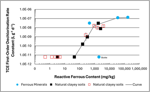
Figure 1: First-order rate constants for abiotic reductive dechlorination of TCE under anaerobic conditions. Circles are data from Schaefer
et al., 2021
[4], filled squares from Schaefer
et al., 2018
[5], and Schaefer
et al., 2017
[6], and open squares from Schaefer
et al., 2025
[1].
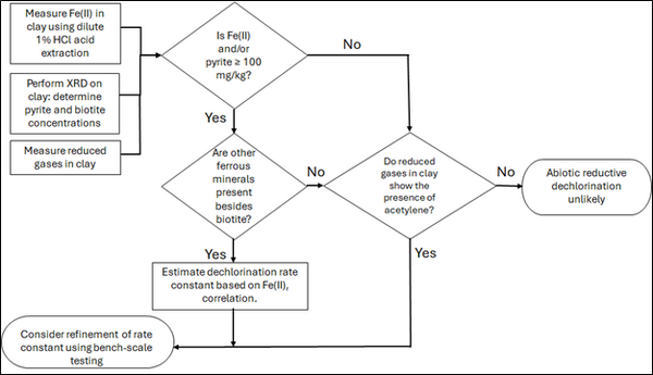
Figure 2: Flowchart diagram of field screening procedures
The recommended approach builds upon the methodology and findings of a recent study[1], emphasizing field-based and analytical techniques to quantify abiotic first-order reductive dechlorination rate constants for PCE and TCE in clayey soils under anoxic conditions. Key components of this evaluation are listed below:
- Zone Identification: The focus of the investigation should be to delineate clayey zones adjacent to hydraulically conductive zones.
- Ferrous Mineral Quantification: Assess ferrous mineral context in clay via 1% HCl extraction at ambient temperature over a 10-minute interval.
- Mineralogical Characterization: Conduct XRD analysis with the specific intent of identifying the presence of pyrite and biotite.
- Reduced Gas Analysis: Measurement of reduced gases such as acetylene, ethene, and ethane concentrations in clay samples. Gas-tight sampling devices (e.g., En Core® soil samplers by En Novative Technologies, Inc.) should be used to ensure sample integrity during collection and transport.
Clay samples should be collected within a few centimeters of the high-permeability interface, with optional additional sampling further inward. For mineralogical analysis, a defined interval may be collected and subsequently subsampled. To preserve sample integrity, exposure to air should be minimized during collection, transport, and handling. Homogenization should occur within an anaerobic chamber, and if subsamples are required for external analysis, they must be shipped in gas-tight, anaerobic containers.
Estimation of the abiotic reductive first-order rate constant for PCE and TCE is based on the “reactive” ferrous content in the clay. Reactive ferrous content (Fe(II)r) is estimated as shown in Equation 1:
- Equation 1: Fe(II)r = DA + XRDpyr - XRDbiotite
where DA is the ferrous content from the dilute acid (1% HCl) extraction, XRDpyr is the pyrite content from XRD analysis, and XRDbiotite is the biotite content from XRD analysis[1].
Abiotic dechlorination is unlikely to contribute to mitigating contaminant back-diffusion when reactive ferrous iron (Fe(II)r) concentrations are below 100 mg/kg (Figure 1). For Fe(II)r above 100 mg/kg, the first-order rate constant for PCE and TCE reductive dechlorination can be estimated using the correlation shown in Figure 1[5][7]. The rate constant exhibits a strong positive correlation with the logarithm of reactive Fe(II) content (Pearson’s r = 0.82), with a slope of 4.7 × 10⁻⁸ L g⁻¹ d⁻¹ (log mg kg⁻¹)⁻¹.
Figure 2 presents a decision flowchart designed to evaluate the significance and extent of abiotic reductive dechlorination. By applying Equation 1 to the dilute acid extractable Fe(II) plus measured mineral species data from clay samples, the reactive ferrous iron content (Fe(II)r) can be quantified, enabling a streamlined assessment of the extent to which abiotic processes are contributing to the mitigation of contaminant back-diffusion.
If Fe(II)r is ≥ 100 mg/kg, a first-order dechlorination rate constant can be estimated and subsequently used within a contaminant fate and transport model. However, if acetylene is detected in the clay, even with Fe(II)r less than 100 mg/kg, then bench-scale testing using methods similar to those described in a recent study[1] is recommended, as such results would likely be inconsistent with those shown in Figure 1, suggesting some other mechanism might be involved, or that the system mineralogy might be more complex than anticipated. Even if Fe(II)r ≥ 100 mg/kg, confirmatory bench-scale testing may be conducted for additional verification and to refine estimation of the abiotic dechlorination rate constant.
Summary and Recommendations
The approach outlined above is intended to serve as a generalized guide for practitioners and site managers to cost-effectively determine the extent to which beneficial abiotic reductive dechlorination reactions are likely occurring in low permeability (e.g., clayey) zones. This approach may be contraindicated if co-contaminants are present. It is currently unclear whether other classes of potentially reactive chemicals, such as trinitrotoluene (TNT) or chlorinated ethanes, could interact competitively with PCE and TCE.
In addition, it remains unclear how other classes of compounds such as per- and polyfluoroalkyl substances (PFAS) may interact or sorb with ferrous minerals and potentially inhibit abiotic dechlorination reactions. Coupling these recommended activities with conventional site investigation tasks would provide an opportunity to perform many of the up-front screening activities with minimal additional project costs. It is important to note that the guidance proposed herein pertains to particularly low permeability media. Sites with complex or varying lithology, where the mineralogy and/or redox conditions may vary, might require evaluation of multiple samples to provide appropriate site-wide information.
References
- ^ 1.0 1.1 1.2 1.3 1.4 Schaefer, C.E., Tran, D., Nguyen, D., Latta, D.E., Werth, C.J., 2025. Evaluating Mineral and In Situ Indicators of Abiotic Dechlorination in Clayey Soils. Groundwater Monitoring and Remediation, 45(2), pp. 31-39. doi: 10.1111/gwmr.12709
- ^ Falta, R., and Wang, W., 2017. A semi-analytical method for simulating matrix diffusion in numerical transport models. Journal of Contaminant Hydrology, 197, pp. 39-49. doi: 10.1016/j.jconhyd.2016.12.007 Open Access Manuscript
- ^ Kulkarni, P.R., Adamson, D.T., Popovic, J., Newell, C.J., 2022. Modeling a well-charactized perfluorooctane sulfate (PFOS) source and plume using the REMChlor-MD model to account for matrix diffusion. Journal of Contaminant Hydrology, 247, Article 103986. doi: 10.1016/j.jconhyd.2022.103986 Open Access Manuscript
- ^ Schaefer, C.E., Ho, P., Berns, E., Werth, C., 2021. Abiotic dechlorination in the presence of ferrous minerals. Journal of Contaminant Hydrology, 241, 103839. doi: 10.1016/j.jconhyd.2021.103839 Open Access Manuscript
- ^ 5.0 5.1 Schaefer, C.E., Ho, P., Berns, E., Werth, C., 2018. Mechanisms for abiotic dechlorination of trichloroethene by ferrous minerals under oxic and anoxic conditions in natural sediments. Environmental Science and Technology, 52(23), pp.13747-13755. doi: 10.1021/acs.est.8b04108
- ^ Schaefer, C.E., Ho., Gurr, C., Berns, E., Werth, C., 2017. Abiotic dechlorination of chlorinated ethenes in natural clayey soils: impacts of mineralogy and temperature. Journal of Contaminant Hydrology, 206, pp. 10-17. doi: 10.1016/j.jconhyd.2017.09.007 Open Access Manuscript
- ^ Borden, R.C., Cha, K.Y., 2021. Evaluating the impact of back diffusion on groundwater cleanup time. Journal of Contaminant Hydrology, 243, Article 103889. doi: 10.1016/j.jconhyd.2021 Open Access Manuscript
See Also

