|
|
| Line 1: |
Line 1: |
| − | ==Sediment Capping== | + | ==Estimating PCE/TCE Abiotic First-Order Reductive Dechlorination Rate Constants in Clayey Soils Under Anoxic Conditions== |
| − | Capping® is an ''in situ'' remedial technology that involves placement of a clean substrate on the surface of [[Contaminated Sediments - Introduction | contaminated sediments]] to reduce contaminant uptake by benthic organisms and contaminant flux to surface water. Simple sand caps can be effective in reducing exposure of benthic organisms and in limiting oxygen transport into the contaminated sediments, resulting in precipitation of metal sulfides. Amendments are sometimes included in caps to reduce cap permeability and groundwater upwelling, to increase contaminant sorption or biodegradation, or to improve habitat.
| + | The U.S. Department of Defense (DoD) faces many challenges in restoring aquifers at contaminated sites, often due to back-diffusion of tetrachloroethene (PCE) and trichloroethene (TCE) from low-permeability clay zones. The uptake, storage, and subsequent long-term release of these dissolved contaminants from clays are key processes in understanding the longevity, intensity, and risks associated with many persistent chlorinated ethene groundwater plumes. Although naturally occurring abiotic and biotic dechlorination processes in clays may reduce stored contaminant mass and significantly aid natural attenuation, no standardized field method currently exists to verify or quantify these reactions. It is critical to remediation design efforts to demonstrate and validate a cost-effective in situ approach for assessing these dechlorination processes using first-order rate constants. An approach was developed and applied across eight DoD sites to support Remedial Project Managers (RPMs) and regulators in evaluating natural attenuation potential in clay-rich environments. |
| | <div style="float:right;margin:0 0 2em 2em;">__TOC__</div> | | <div style="float:right;margin:0 0 2em 2em;">__TOC__</div> |
| | | | |
| | '''Related Article(s):''' | | '''Related Article(s):''' |
| − | *[[Contaminated Sediments - Introduction]]
| |
| − | *[[In Situ Treatment of Contaminated Sediments with Activated Carbon]]
| |
| − | *Sediment Risk Assessment
| |
| − | *[[Passive Sampling of Sediments]]
| |
| | | | |
| − | '''Contributor(s):'''
| + | *[[Monitored Natural Attenuation (MNA)]] |
| − | *Danny Reible | + | *[[Monitored Natural Attenuation (MNA) of Chlorinated Solvents]] |
| | + | *[[Monitored Natural Attenuation - Transitioning from Active Remedies]] |
| | + | *[[Matrix Diffusion]] |
| | + | *[[REMChlor - MD]] |
| | | | |
| − | '''Key Resource(s):''' | + | '''Contributors:''' Dani Tran, Dr. Charles Schaefer, Dr. Charles Werth |
| − | *Processes, Assessment and Remediation of Contaminated Sediments<ref name="Reible2014">Reible, D. D., Editor, 2014. Processes, Assessment and Remediation of Contaminated Sediments. Springer, New York, NY. 462 pp. ISBN: 978-1-4614-6725-0</ref>
| |
| | | | |
| − | * Guidance for In-Situ Subaqueous Capping of Contaminated Sediments<ref name="Palermo1998">Palermo, M., Maynord, S., Miller, J. and Reible, D., 1998. Guidance for In-Situ Subaqueous Capping of Contaminated Sediments. Assessment and Remediation of Contaminated Sediments (ARCS) Program, Great Lakes National Program Office, US EPA 905-B96-004. 147 pp. [[Media: USEPA_905-B96-004.pdf | Report.pdf]]</ref> | + | '''Key Resource:''' |
| | + | *Schaefer, C.E, Tran, D., Nguyen, D., Latta, D.E., Werth, C.J., 2025. Evaluating Mineral and In Situ Indicators of Abiotic Dechlorination in Clayey Soils<ref name="SchaeferEtAl2025"/> |
| | | | |
| | ==Introduction== | | ==Introduction== |
| − | [[File:SedCapFig1.png|thumb|left|470px|Figure 1. Conceptual sketch of a cap configuration]]
| + | Cost-effective methods are needed to verify the occurrence of natural dechlorination processes and quantify their dechlorination rates in clays under ambient in situ conditions in order to reliably predict their long-term influence on plume longevity and mass discharge. However, accurately determining these rates is challenging due to slow reaction kinetics, the transient nature of transformation products, and the interplay of biotic and abiotic mechanisms within the clay matrix or at clay-sand interfaces. Tools capable of quantifying these reactions and assessing their role in mitigating plume persistence would be a significant aid for long-term site management. |
| − | Capping is an ''in situ'' remedial technology for contaminated sediments that involves placement of a clean substrate on the sediment surface. Capping contaminated sediments following [[Wikipedia: Dredging | dredging operations]] and capping of dredged material to stabilize contaminants has been a common practice by the United States Army Corps of Engineers since the 1970s. Beginning in the 1980s, in Japan and subsequently elsewhere, capping has been used more widely as a remedial approach to improve the quality of the bottom substrate and reduce contaminant exposures to benthic organisms and fish. The USEPA published a capping guidance document in 1998 that summarizes past uses of sediment capping and outlines its basic design<ref name="Palermo1998"/>. Although capping technology has developed substantially in the past 20 years, this early reference still provides useful information on the approach and its applications. A more recent summary of capping is described in Reible 2014<ref name="Reible2014"/>.
| |
| | | | |
| − | Capping serves to contain contaminated sediment solids, isolate contaminants from benthic organisms and reduce contaminant transport to the sediment surface and overlying water. The clean substrate may be an inert material such as sand, a natural sorbing material such as other sediments or clays, or be amended with an active/reactive material to enhance the isolation of the contaminants. Amendments to enhance contaminant isolation include permeability reduction agents to divert groundwater flow, sorbents to retard contaminant migration through the capping layer or provide greater accumulation capacity, or reagents to encourage degradation or transformation of the contaminants.
| + | For reductive abiotic dechlorination under anoxic conditions, a 1% hydrochloric acid (HCl) extraction of a sample of native clay coupled with X-ray diffraction (XRD) data can be used as a screening level tool to estimate reductive dechlorination rate constants. These rate constants can be inserted into fate and transport models such as [[REMChlor - MD]]<ref>Falta, R., and Wang, W., 2017. A semi-analytical method for simulating matrix diffusion in numerical transport models. Journal of Contaminant Hydrology, 197, pp. 39-49. [https://doi.org/10.1016/j.jconhyd.2016.12.007 doi: 10.1016/j.jconhyd.2016.12.007] [[Media: FaltaWang2017.pdf | Open Access Manuscript]]</ref><ref>Kulkarni, P.R., Adamson, D.T., Popovic, J., Newell, C.J., 2022. Modeling a well-charactized perfluorooctane sulfate (PFOS) source and plume using the REMChlor-MD model to account for matrix diffusion. Journal of Contaminant Hydrology, 247, Article 103986. [https://doi.org/10.1016/j.jconhyd.2022.103986 doi: 10.1016/j.jconhyd.2022.103986] [[Media: KulkarniEtAl2022.pdf | Open Access Manuscript]]</ref> to quantify abiotic dechlorination impacts within clay aquitards on chlorinated solvent plumes. Thus, determination of the abiotic reductive dechlorination rate constant for a particular clayey soil can be readily utilized to provide a more accurate assessment of aquifer cleanup timeframes for groundwater plumes that are being sustained by contaminant back-diffusion. |
| | | | |
| − | The basic concept of a cap is illustrated in Figure 1. The Figure also illustrates that a cap is often a thin layer or layers relative to water depth and generally causes little disturbance to the underlying sediments or body of water in which it is placed. Depending upon the erosive forces to which the cap may be subjected, the surface layer may be composed of relatively coarse material to withstand those erosive forces.
| + | ==Recommended Approach== |
| | + | [[File: TranFig1.png | thumb | 500 px | Figure 1: First-order rate constants for abiotic reductive dechlorination of TCE under anaerobic conditions. Circles are data from Schaefer ''et al.'', 2021<ref>Schaefer, C.E., Ho, P., Berns, E., Werth, C., 2021. Abiotic dechlorination in the presence of ferrous minerals. Journal of Contaminant Hydrology, 241, 103839. [https://doi.org/10.1016/j.jconhyd.2021.103839 doi: 10.1016/j.jconhyd.2021.103839] [[Media: SchaeferEtAl2021.pdf | Open Access Manuscript]]</ref>, filled squares from Schaefer ''et al.'', 2018<ref name="SchaeferEtAl2018"/>, and Schaefer ''et al.'', 2017<ref>Schaefer, C.E., Ho., Gurr, C., Berns, E., Werth, C., 2017. Abiotic dechlorination of chlorinated ethenes in natural clayey soils: impacts of mineralogy and temperature. Journal of Contaminant Hydrology, 206, pp. 10-17. [https://doi.org/10.1016/j.jconhyd.2017.09.007 doi: 10.1016/j.jconhyd.2017.09.007] [[Media: SchaeferEtAl2017.pdf | Open Access Manuscript]]</ref>, and open squares from Schaefer ''et al.'', 2025<ref name="SchaeferEtAl2025"/>. ]] |
| | + | [[File: TranFig2.png | thumb | 600 px | Figure 2: Flowchart diagram of field screening procedures]] |
| | + | The recommended approach builds upon the methodology and findings of a recent study<ref name="SchaeferEtAl2025">Schaefer, C.E., Tran, D., Nguyen, D., Latta, D.E., Werth, C.J., 2025. Evaluating Mineral and In Situ Indicators of Abiotic Dechlorination in Clayey Soils. Groundwater Monitoring and Remediation, 45(2), pp. 31-39. [https://doi.org/10.1111/gwmr.12709 doi: 10.1111/gwmr.12709]</ref>, emphasizing field-based and analytical techniques to quantify abiotic first-order reductive dechlorination rate constants for PCE and TCE in clayey soils under anoxic conditions. Key components of this evaluation are listed below: |
| | + | #<u>Zone Identification:</u> The focus of the investigation should be to delineate clayey zones adjacent to hydraulically conductive zones. |
| | + | #<u>Ferrous Mineral Quantification:</u> Assess ferrous mineral context in clay via 1% HCl extraction at ambient temperature over a 10-minute interval. |
| | + | #<u>Mineralogical Characterization:</u> Conduct XRD analysis with the specific intent of identifying the presence of pyrite and biotite. |
| | + | #<u>Reduced Gas Analysis:</u> Measurement of reduced gases such as acetylene, ethene, and ethane concentrations in clay samples. Gas-tight sampling devices (e.g., En Core® soil samplers by En Novative Technologies, Inc.) should be used to ensure sample integrity during collection and transport. |
| | | | |
| − | Although a cap is typically thin compared to the water depth, it generally must be thicker than the biologically active zone (BAZ) of the sediments. The biologically active zone is that zone in which benthic organisms live and interact with the sediment. Their activities tend to mix the BAZ (known as [[Wikipedia: Bioturbation | bioturbation]]) over the course of a few years and thus a cap that is thinner than the BAZ will tend to become intermixed with the underlying contaminated sediments. Processes other than bioturbation including diffusion, advection or groundwater upwelling, hyporheic exchange near the interface, biogenic gas production and migration and underlying sediment consolidation can all lead to contaminant migration into and through a cap. These occur at different rates and intensities and their assessment and evaluation ultimately governs the effectiveness of a cap and the feasibility of its use as a sediment remediation technology for a particular site.
| + | Clay samples should be collected within a few centimeters of the high-permeability interface, with optional additional sampling further inward. For mineralogical analysis, a defined interval may be collected and subsequently subsampled. To preserve sample integrity, exposure to air should be minimized during collection, transport, and handling. Homogenization should occur within an anaerobic chamber, and if subsamples are required for external analysis, they must be shipped in gas-tight, anaerobic containers. |
| | | | |
| − | In general, capping is an effective remedial technology for contaminants that are strongly associated with the sediment solids including hydrophobic organic compounds such as high molecular weight [[Polycyclic Aromatic Hydrocarbons (PAHs) | polycyclic aromatic hydrocarbons (PAHs)]], [[Wikipedia: Polychlorinated biphenyl | polychlorinated biphenyls (PCBs)]], [[Wikipedia: Dioxins and dioxin-like compounds | dioxins]] and [[Wikipedia: DDT | DDTx]], but also [[Metal and Metalloid Contaminants | heavy metals]]. Hydrophobic organic compounds tend to strongly associate with the organic fraction of sediments so organic rich sediments or the addition of organic phases to the capping material can be very effective at containing these contaminants. Many of the common heavy metals of concern, including cadmium, copper, nickel, zinc, lead and mercury, tend to be associated with insoluble sulfides under strongly reducing conditions. Since oxygen penetration into a capping layer is typically limited to a few cm or less at the surface, a cap serves to drive the underlying contaminated sediment toward strongly reducing conditions and, particularly in marine and estuarine sediments, encourage sulfate reduction leading to the formation of these insoluble sulfides. The low solubility of these sulfides encourages retention by a capping layer and makes the cap extremely effective as a remedial approach for sediments with elevated concentrations of heavy metals.
| + | Estimation of the abiotic reductive first-order rate constant for PCE and TCE is based on the “reactive” ferrous content in the clay. Reactive ferrous content (Fe(II)<sub>r</sub>) is estimated as shown in Equation 1: |
| | | | |
| − | A variety of tools have been developed to evaluate the processes leading to sorption and retardation of contaminants as well as processes leading to contaminant migration and release. The original references quantifying contaminant behavior in a sediment cap were explored in a series of papers in the early 1990s<ref name="Wang1991">Wang, X.Q., Thibodeaux, L.J., Valsaraj, K.T. and Reible, D.D., 1991. Efficiency of Capping Contaminated Bed Sediments in Situ. 1. Laboratory-Scale Experiments on Diffusion-Adsorption in the Capping Layer. Environmental Science and Technology, 25(9), pp.1578-1584. [https://doi.org/10.1021/es00021a008 DOI: 10.1021/es00021a008]</ref><ref name="Thoma1993">Thoma, G.J., Reible, D.D., Valsaraj, K.T. and Thibodeaux, L.J., 1993. Efficiency of Capping Contaminated Bed Sediments in Situ 2. Mathematics of Diffusion-Adsorption in the Capping Layer. Environmental Science and Technology, 27(12), pp.2412-2419. [https://doi.org/10.1021/es00048a015 DOI: 10.1021/es00048a015]</ref>. Since that time, design tools have been continuously improved. [https://www.depts.ttu.edu/ceweb/research/reiblesgroup/downloads.php CapSim] is a commonly used and current tool developed by Dr. Reible and collaborators. This tool can evaluate contaminant release from uncapped, capped, and treated sediments for purposes of design and evaluation. The model formulation and structure is described in Shen et al. 2018<ref name="Shin2018">Shen, X., Lampert, D., Ogle, S. and Reible, D., 2018. A software tool for simulating contaminant transport and remedial effectiveness in sediment environments. Environmental Modelling and Software, 109, pp. 104-113. [https://doi.org/10.1016/j.envsoft.2018.08.014 DOI: 10.1016/j.envsoft.2018.08.014]</ref>. One common use of such a tool is to evaluate the effect of various cap materials and thicknesses on the performance of a cap.
| + | ::'''Equation 1:''' <big>''Fe(II)<sub><small>r</small></sub> = DA + XRD<sub><small>pyr</small></sub> - XRD<sub><small>biotite</small></sub>''</big> |
| | | | |
| − | ==Cap Design and Materials for Chemical Containment==
| + | where ''DA'' is the ferrous content from the dilute acid (1% HCl) extraction, ''XRD<sub><small>pyr</small></sub>'' is the pyrite content from XRD analysis, and ''XRD<sub><small>biotite</small></sub>'' is the biotite content from XRD analysis<ref name="SchaeferEtAl2025"/>. |
| − | An inert material such as sand can be effective as a capping material where contaminants are strongly associated with solids and where the operative site specific transport mechanisms do not lead to rapid contaminant migration through such a material. Additional contaminant containment can often be achieved through the placement of clean sediment, e.g. dredged material from a nearby location. Other materials as cap layers or amendments may be useful to address particularly mobile contaminants or when particular degradative mechanisms can be exploited. The Anacostia River was the site of a demonstration that first tested “active” or “amended” capping in the field<ref name="Reible2003">Reible, D., Constant, D.W., Roberts, K. and Zhu, Y., 2003. Active capping demonstration project in anacostia DC. In Second International Conference on the Remediation of Contaminated Sediments: October. Free download available from: [https://www.researchgate.net/profile/Danny-Reible/publication/237747790_ACTIVE_CAPPING_DEMONSTRATION_PROJECT_IN_ANACOSTIA_DC/links/0c96053861030b7699000000/ACTIVE-CAPPING-DEMONSTRATION-PROJECT-IN-ANACOSTIA-DC.pdf ResearchGate]</ref><ref name="Reible2006">Reible, D., Lampert, D., Constant, D., Mutch Jr, R.D. and Zhu, Y., 2006. Active Capping Demonstration in the Anacostia River, Washington, DC. Remediation Journal: The Journal of Environmental Cleanup Costs, Technologies and Techniques, 17(1), pp. 39-53. [https://doi.org/10.1002/rem.20111 DOI: 10.1002/rem.20111] Free download available from: [https://www.academia.edu/download/44146457/Remediation_Journal_Paper_2006.pdf Academia.edu]</ref>. Amended caps are often the best option when groundwater upwelling or other advective processes promote significant mobility of contaminants and the addition of sorbents can slow that contaminant migration<ref name="Ghosh2011">Ghosh, U., Luthy, R.G., Cornelissen, G., Werner, D. and Menzie, C.A., 2011. In-situ Sorbent Amendments: A New Direction in Contaminated Sediment Management. Environmental Science and Technology, 45(4), pp. 1163-1168. [https://doi.org/10.1021/es102694h DOI: 10.1021/es102694h] Open access article from: [https://pubs.acs.org/doi/pdf/10.1021/es102694h American Chemical Society] [[Media: Ghosh2011.pdf | Report.pdf]]</ref>. Although a variety of materials have been proposed for sediment caps, a far smaller number of options have been successfully employed in the field.
| |
| − |
| |
| − | Metals migration is very site dependent due to the potential for many metals to complex with other species in the interstitial water and the specific metal speciation present at a site. Often, the strongly reducing environment beneath a cap renders many common metals unavailable through the formation of metal sulfides. In such cases, a simple sand cap can be very effective. Amended caps to manage metal contaminated sediments may be advantageous when site specific conditions lead to elevated metals mobility, but should be supported with site specific testing<ref name="Viana2008">Viana, P.Z., Yin, K. and Rockne, K.J., 2008. Modeling Active Capping Efficacy. 1. Metal and Organometal Contaminated Sediment Remediation. Environmental Science and Technology, 42(23), pp. 8922-8929. [https://doi.org/10.1021/es800942t DOI: 10.1021/es800942t]</ref>.
| |
| | | | |
| − | For hydrophobic organic contaminants, cap amendments that directly control groundwater upwelling and also sorbents that can remove migrating contaminants from that groundwater have been successfully employed. Examples include clay materials such as AquaBlok<sup>®</sup> for permeability control, sorbents such as [[Wikipedia: Activated carbon | activated carbon]] for truly dissolved contaminants, and [[Wikipedia: Organoclay | organophilic clays]] for separate phase contaminants. | + | Abiotic dechlorination is unlikely to contribute to mitigating contaminant back-diffusion when reactive ferrous iron (Fe(II)<sub><small>r</small></sub>) concentrations are below 100 mg/kg (Figure 1). For Fe(II)<sub><small>r</small></sub> above 100 mg/kg, the first-order rate constant for PCE and TCE reductive dechlorination can be estimated using the correlation shown in Figure 1<ref name="SchaeferEtAl2018">Schaefer, C.E., Ho, P., Berns, E., Werth, C., 2018. Mechanisms for abiotic dechlorination of trichloroethene by ferrous minerals under oxic and anoxic conditions in natural sediments. Environmental Science and Technology, 52(23), pp.13747-13755. [https://doi.org/10.1021/acs.est.8b04108 doi: 10.1021/acs.est.8b04108]</ref><ref>Borden, R.C., Cha, K.Y., 2021. Evaluating the impact of back diffusion on groundwater cleanup time. Journal of Contaminant Hydrology, 243, Article 103889. [https://doi.org/10.1016/j.jconhyd.2021.103889 doi: 10.1016/j.jconhyd.2021] [[Media: BordenCha2021.pdf | Open Access Manuscript]]</ref>. The rate constant exhibits a strong positive correlation with the logarithm of reactive Fe(II) content (Pearson’s ''r'' = 0.82), with a slope of 4.7 × 10⁻⁸ L g⁻¹ d⁻¹ (log mg kg⁻¹)⁻¹. |
| | | | |
| − | The placement of clean sediment as an ''in situ'' cap can be difficult when the material is fine grained or has a low density. Capping with a layer of coarse grained material such as clean sand mitigates this issue although clean sands have minimal sorption capacity. Because of this limitation, sand caps may not be sufficient for achieving remedial goals in sites where contamination levels are high or transport rates are fast due to pore water upwelling or tidal pumping effects. Conditions such as these may require the use of “active” amendments to reduce transport rates.
| + | Figure 2 presents a decision flowchart designed to evaluate the significance and extent of abiotic reductive dechlorination. By applying Equation 1 to the dilute acid extractable Fe(II) plus measured mineral species data from clay samples, the reactive ferrous iron content (Fe(II)<sub><small>r</small></sub>) can be quantified, enabling a streamlined assessment of the extent to which abiotic processes are contributing to the mitigation of contaminant back-diffusion. |
| − |
| |
| − | Capping with clean sand provides a physical barrier between the underlying contaminated material and the overlying water, stabilizes the underlying sediment to prevent re-suspension of contaminated particles, and can reduce chemical exposure under certain conditions. Sand primarily provides a passive barrier to the downward penetration of bioturbating organisms and the upward movement of sediment or contaminants. Although conventional sandy caps can often be an effective means of managing contaminated sediments, there are conditions when sand caps may not be capable of achieving design objectives. Some factors that reduce the effectiveness of sand caps include:
| |
| | | | |
| − | *erosion and loss of cap integrity
| + | If Fe(II)r is ≥ 100 mg/kg, a first-order dechlorination rate constant can be estimated and subsequently used within a contaminant fate and transport model. However, if acetylene is detected in the clay, even with Fe(II)r less than 100 mg/kg, then bench-scale testing using methods similar to those described in a recent study<ref name="SchaeferEtAl2025"/> is recommended, as such results would likely be inconsistent with those shown in Figure 1, suggesting some other mechanism might be involved, or that the system mineralogy might be more complex than anticipated. Even if Fe(II)r ≥ 100 mg/kg, confirmatory bench-scale testing may be conducted for additional verification and to refine estimation of the abiotic dechlorination rate constant. |
| − | *high groundwater upwelling rates
| |
| − | *mobile (low sorption) contaminants of concern (COCs)
| |
| − | *high COC concentrations
| |
| − | *unusually toxic COCs
| |
| − | *the presence of tidal influences
| |
| − | *the presence of non-aqueous phase liquids (NAPLs)
| |
| − | *high rates of gas ebullition
| |
| | | | |
| − | Of these, the first three are common limitations to capping and often control the ability to effectively design and implement a cap as a sediment remedial strategy. In these cases, it may be possible to offset these issues by increasing the thickness of the cap. However, the required thickness can reach infeasible levels in shallow streams or navigable water bodies. In addition, increased construction costs associated with thick caps may become prohibitive. As a result of these issues, caps that use alternative materials (also known as active caps) to reduce the thickness or increase the protectiveness of a cap may be necessary. The materials in active caps are designed to interact with the COCs to enhance the containment properties of the cap.
| + | ==Summary and Recommendations== |
| | + | The approach outlined above is intended to serve as a generalized guide for practitioners and site managers to cost-effectively determine the extent to which beneficial abiotic reductive dechlorination reactions are likely occurring in low permeability (e.g., clayey) zones. This approach may be contraindicated if co-contaminants are present. It is currently unclear whether other classes of potentially reactive chemicals, such as trinitrotoluene (TNT) or chlorinated ethanes, could interact competitively with PCE and TCE. |
| | | | |
| − | [[Wikipedia: Apatite | Apatites]] are a class of naturally occurring minerals that have been investigated as a sorbent for metals in soils and sediments<ref name="Melton2003">Melton, J.S., Crannell, B.S., Eighmy, T.T., Wilson, C. and Reible, D.D., 2003. Field Trial of the UNH Phosphate-Based Reactive Barrier Capping System for the Anacostia River. EPA Grant R819165-01-0</ref><ref name="Reible2003"/><ref name="Knox2012">Knox, A.S., Paller, M.H. and Roberts, J., 2012. Active Capping Technology—New Approaches for In Situ Remediation of Contaminated Sediments. Remediation Journal, 22(2), pp.93-117. [https://doi.org/10.1002/rem.21313 DOI: 10.1002/rem.21313] Free download available from: [https://www.researchgate.net/profile/Anna-Knox-2/publication/233374607_Active_Capping_Technology-New_Approaches_for_In_Situ_Remediation_of_Contaminated_Sediments/links/5a7de4c5aca272a73765c344/Active-Capping-Technology-New-Approaches-for-In-Situ-Remediation-of-Contaminated-Sediments.pdf ResearchGate]</ref>. Apatites consist of a matrix of calcium phosphate and various other common anions, including fluoride, chloride, hydroxide, and occasionally carbonate. Metals are sequestered either through direct ion exchange with the calcium atom or dissolution of hydroxyapatite followed by precipitation of lead apatite. [[Wikipedia: Zeolite | Zeolites]], which are microporous aluminosilicate minerals with a high cationic exchange capacity (CEC), have also been proposed to manage metal species<ref name="Zhan2019">Zhan, Y., Yu, Y., Lin, J., Wu, X., Wang, Y. and Zhao, Y., 2019. Simultaneous control of nitrogen and phosphorus release from sediments using iron-modified zeolite as capping and amendment materials. Journal of Environmental Management, 249, p.109369. [https://doi.org/10.1016/j.jenvman.2019.109369 DOI: 10.1016/j.jenvman.2019.109369]</ref>.
| + | In addition, it remains unclear how other classes of compounds such as per- and polyfluoroalkyl substances (PFAS) may interact or sorb with ferrous minerals and potentially inhibit abiotic dechlorination reactions. Coupling these recommended activities with conventional site investigation tasks would provide an opportunity to perform many of the up-front screening activities with minimal additional project costs. It is important to note that the guidance proposed herein pertains to particularly low permeability media. Sites with complex or varying lithology, where the mineralogy and/or redox conditions may vary, might require evaluation of multiple samples to provide appropriate site-wide information. |
| − |
| |
| − | It is possible to create a hydrophobic, sorbing layer for non-polar organics by exchanging a cationic surfactant onto the surface of clays such as zeolites and bentonites,. Organoclay is a modified bentonite containing such substitutions that has been evaluated for control of non-aqueous phase NAPLs and other organic contaminants<ref name="Reible2007">Reible, D.D., Lu, X., Moretti, L., Galjour, J. and Ma, X., 2007. Organoclays for the capping of contaminated sediments. AIChE Annual Meeting. ISBN: 978-081691022-9</ref>. An organoclay cap has been implemented for sediment remediation at the McCormick and Baxter site in Portland, OR<ref name="Parrett2005">Parrett, K. and Blishke, H., 2005. 23-Acre Multilayer Sediment Cap in Dynamic Riverine Environment Using Organoclay an Adsorptive Capping Material. Presentation to Society of Environmental Toxicology and Chemistry (SETAC), 26th Annual Meeting.</ref>. A similar organic sorbing phase can be formed by treating zeolites with surfactants but this approach has not been reported for contaminated sediments. | |
| | | | |
| − | Activated carbon is a strong sorbent of hydrophobic organic compounds and has been used as a [[In Situ Treatment of Contaminated Sediments with Activated Carbon | treatment for sediments]] or as an active sorbent within a capping layer<ref name="Zimmerman2004">Zimmerman, J.R., Ghosh, U., Millward, R.N., Bridges, T.S. and Luthy, R.G., 2004. Addition of Carbon Sorbents to Reduce PCB and PAH Bioavailability in Marine Sediments: Physicochemical Tests. Environmental Science and Technology, 38(20), pp. 5458-5464. [https://doi.org/10.1021/es034992v DOI: 10.1021/es034992v]</ref><ref name="Werner2005">Werner, D., Higgins, C.P. and Luthy, R.G., 2005. The sequestration of PCBs in Lake Hartwell sediment with activated carbon. Water Research, 39(10), pp. 2105-2113. [https://doi.org/10.1016/j.watres.2005.03.019 DOI: 10.1016/j.watres.2005.03.019]</ref><ref name="Abel2018">Abel, S. and Akkanen, J., 2018. A Combined Field and Laboratory Study on Activated Carbon-Based Thin Layer Capping in a PCB-Contaminated Boreal Lake. Environmental Science and Technology, 52(8), pp. 4702-4710. [https://doi.org/10.1021/acs.est.7b05114 DOI: 10.1021/acs.est.7b05114] Open access article available from: [https://pubs.acs.org/doi/pdf/10.1021/acs.est.7b05114 American Chemical Society] [[Media: Abel2018.pdf | Report.pdf]]</ref><ref name="Payne 2018">Payne, R.B., Ghosh, U., May, H.D., Marshall, C.W. and Sowers, K.R., 2019. A Pilot-Scale Field Study: In Situ Treatment of PCB-Impacted Sediments with Bioamended Activated Carbon. Environmental Science and Technology, 53(5), pp. 2626-2634. [https://doi.org/10.1021/acs.est.8b05019 DOI: 10.1021/acs.est.8b05019]</ref><ref name="Yan2020">Yan, S., Rakowska, M., Shen, X., Himmer, T., Irvine, C., Zajac-Fay, R., Eby, J., Janda, D., Ohannessian, S. and Reible, D.D., 2020. Bioavailability Assessment in Activated Carbon Treated Coastal Sediment with In situ and Ex situ Porewater Measurements. Water Research, 185, p. 116259. [https://doi.org/10.1016/j.watres.2020.116259 DOI: 10.1016/j.watres.2020.116259]</ref>. Placement of activated carbon for sediment capping is difficult due to the near neutral buoyancy of the material but it has been applied in this manner in relatively low energy environments such as Onondaga Lake, Syracuse, NY<ref name="Vlassopoulos2017">Vlassopoulos, D., Russell, K., Larosa, P., Brown, R., Mohan, R., Glaza, E., Drachenberg, T., Reible, D., Hague, W., McAuliffe, J. and Miller, S., 2017. Evaluation, Design, and Construction of Amended Reactive Caps to Restore Onondaga Lake, Syracuse, New York, USA. Journal of Marine Environmental Engineering, 10(1), pp. 13-27. Free download available from: [https://www.researchgate.net/publication/317762995_Evaluation_design_and_construction_of_amended_reactive_caps_to_restore_Onondaga_lake_Syracuse_New_York_USA ResearchGate]</ref>. Alternatives in higher energy environments include placement of activated carbon in a mat such as the CETCO Reactive Core Mat (RCM)<sup>®</sup> or Huesker Tektoseal<sup>®</sup>, or as a composite material such as SediMite<sup>®</sup> or AquaGate<sup>®</sup>. In the case of the mats, powdered or granular activated carbon can be placed in a controlled layer while the density of the composite materials is such that they can be broadcast from the surface and allowed to settle to the bottom. In a sediment treatment application, the composite material would either be worked into the surface or allowed to intermix gradually by bioturbation and other processes. In a capping application, the mat or composite material would typically be combined or overlain with a sand or other capping layer to keep it in place and to provide a chemical isolation layer away from the sediment surface.
| + | <br clear="right"/> |
| − | | |
| − | As an alternative to a sorptive capping amendment, low-permeability cap amendments have been proposed to enhance cap design life by decreasing pore water advection. Low permeability clays are an effective means to divert upwelling groundwater away from a contaminated sediment area but are difficult to place in the aqueous environment. Bentonite clays can be placed in mats similar to what is done to provide a low permeability liner in landfills. There are also commercial products that can place clays directly such as the composite material AquaBlok<sup>®</sup>, a bentonite clay and polymer based mineral around an aggregate core<ref name="Barth2008">Barth, E.F., Reible, D. and Bullard, A., 2008. Evaluation of the physical stability, groundwater seepage control, and faunal changes associated with an AquaBlok<sup>®</sup> sediment cap. Remediation: The Journal of Environmental Cleanup Costs, Technologies and Techniques, 18(4), pp.63-70. [https://doi.org/10.1002/rem.20183 DOI: 10.1002/rem.20183]</ref>.
| |
| − |
| |
| − | Sediment caps become colonized by microorganisms from the sediments and surface water and potentially become a zone of pollutant biotransformation over time. Aerobic degradation occurs only near the solids-water interface in which benthic organisms are active and thus there might still be significant benthic organism exposure to contaminants. Biotransformation in the anaerobic zone of a cap, which typically extends well beyond the zone of benthic activity, could significantly reduce the risk of pollutant exposure but successful caps encouraging deep degradation processes have not been demonstrated beyond the laboratory. The addition of materials such as nutrients and oxygen releasing compounds for enhancing the attenuation of contaminants through biodegradation has also been assessed but not applied in the field. Short term improvements in biodegradation rates can be achieved through tailoring of conditions or addition of nutrients but long term efficacy has not been demonstrated<ref name="Pagnozzi2020">Pagnozzi, G., Carroll, S., Reible, D.D. and Millerick, K., 2020. Biological Natural Attenuation and Contaminant Oxidation in Sediment Caps: Recent Advances and Future Opportunities. Current Pollution Reports, pp.1-14. [https://doi.org/10.1007/s40726-020-00153-5 DOI: 10.1007/s40726-020-00153-5]</ref>.
| |
| − | [[File: SedCapFig2.png | thumb |600px|Figure 2. A conceptualization of a cap with accompanying habitat layer]]
| |
| − | | |
| − | ==Cap Design and Materials for Habitat Restoration==
| |
| − | In addition to providing chemical isolation and containment, a cap can also be used to provide improvements for organisms by enhancing the habitat characteristics of the bottom substrate<ref name="Yozzo2004">Yozzo, D.J., Wilber, P. and Will, R.J., 2004. Beneficial use of dredged material for habitat creation, enhancement, and restoration in New York–New Jersey Harbor. Journal of Environmental Management, 73(1), pp. 39-52. [https://doi.org/10.1016/j.jenvman.2004.05.008 DOI: 10.1016/j.jenvman.2004.05.008]</ref><ref name="Zhang2016">Zhang, C., Zhu, M.Y., Zeng, G.M., Yu, Z.G., Cui, F., Yang, Z.Z. and Shen, L.Q., 2016. Active capping technology: a new environmental remediation of contaminated sediment. Environmental Science and Pollution Research, 23(5), pp.4370-4386. [https://doi.org/10.1007/s11356-016-6076-8 DOI: 10.1007/s11356-016-6076-8]</ref><ref name="Vlassopoulos2017"/>. Often, contaminated sediment environments are degraded for a variety of reasons in addition to the toxic constituents. One way to overcome this is to provide both a habitat layer and chemical isolation or contaminant capping layer. Figure 2 illustrates just such a design providing a more appropriate habitat enhancing substrate, in this case by incorporation additional organic material, vegetation and debris, which is often used by fish species for protection, into the surface layer. In a high energy environment, it should be recognized that it may not be possible to keep a suitable habitat layer in place during high flow events. This would be true of suitable habitat that had developed naturally as well as a constructed habitat layer and it is presumed that if such a habitat is the normal condition of the waterbody that it will recover over time between such high flow events.
| |
| − | | |
| − | ==Summary==
| |
| − | Clean substrate can be placed at the sediment-water interface for the purposes of reducing exposure to and risk from contaminants in the sediments. The cap can consist of simple materials such as sand designed to physically stabilize contaminated sediments and separate the benthic community from those contaminants or may include other materials designed to sequester contaminants even under adverse conditions including strong groundwater upwelling or highly mobile contaminants. The surface of a cap may be designed of coarse material such as gravel or cobble to be stable under high flow events or designed to be more appropriate habitat for benthic and aquatic organisms. As a result of its flexibility, simplicity and low cost relative to its effectiveness, capping is one of the most prevalent remedial technologies for sediments.
| |
| | | | |
| | ==References== | | ==References== |
| Line 74: |
Line 55: |
| | | | |
| | ==See Also== | | ==See Also== |
| | + | *[https://serdp-estcp.mil/projects/details/a7e3f7b5-ed82-4591-adaa-6196ff33dd60 ESTCP Project ER20-5031 – In Situ Verification and Quantification of Naturally Occurring Dechlorination Rates in Clays: Demonstrating Processes that Mitigate Back-Diffusion and Plume Persistence] |
Estimating PCE/TCE Abiotic First-Order Reductive Dechlorination Rate Constants in Clayey Soils Under Anoxic Conditions
The U.S. Department of Defense (DoD) faces many challenges in restoring aquifers at contaminated sites, often due to back-diffusion of tetrachloroethene (PCE) and trichloroethene (TCE) from low-permeability clay zones. The uptake, storage, and subsequent long-term release of these dissolved contaminants from clays are key processes in understanding the longevity, intensity, and risks associated with many persistent chlorinated ethene groundwater plumes. Although naturally occurring abiotic and biotic dechlorination processes in clays may reduce stored contaminant mass and significantly aid natural attenuation, no standardized field method currently exists to verify or quantify these reactions. It is critical to remediation design efforts to demonstrate and validate a cost-effective in situ approach for assessing these dechlorination processes using first-order rate constants. An approach was developed and applied across eight DoD sites to support Remedial Project Managers (RPMs) and regulators in evaluating natural attenuation potential in clay-rich environments.
Related Article(s):
Contributors: Dani Tran, Dr. Charles Schaefer, Dr. Charles Werth
Key Resource:
- Schaefer, C.E, Tran, D., Nguyen, D., Latta, D.E., Werth, C.J., 2025. Evaluating Mineral and In Situ Indicators of Abiotic Dechlorination in Clayey Soils[1]
Introduction
Cost-effective methods are needed to verify the occurrence of natural dechlorination processes and quantify their dechlorination rates in clays under ambient in situ conditions in order to reliably predict their long-term influence on plume longevity and mass discharge. However, accurately determining these rates is challenging due to slow reaction kinetics, the transient nature of transformation products, and the interplay of biotic and abiotic mechanisms within the clay matrix or at clay-sand interfaces. Tools capable of quantifying these reactions and assessing their role in mitigating plume persistence would be a significant aid for long-term site management.
For reductive abiotic dechlorination under anoxic conditions, a 1% hydrochloric acid (HCl) extraction of a sample of native clay coupled with X-ray diffraction (XRD) data can be used as a screening level tool to estimate reductive dechlorination rate constants. These rate constants can be inserted into fate and transport models such as REMChlor - MD[2][3] to quantify abiotic dechlorination impacts within clay aquitards on chlorinated solvent plumes. Thus, determination of the abiotic reductive dechlorination rate constant for a particular clayey soil can be readily utilized to provide a more accurate assessment of aquifer cleanup timeframes for groundwater plumes that are being sustained by contaminant back-diffusion.
Recommended Approach
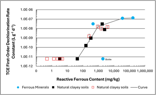
Figure 1: First-order rate constants for abiotic reductive dechlorination of TCE under anaerobic conditions. Circles are data from Schaefer
et al., 2021
[4], filled squares from Schaefer
et al., 2018
[5], and Schaefer
et al., 2017
[6], and open squares from Schaefer
et al., 2025
[1].
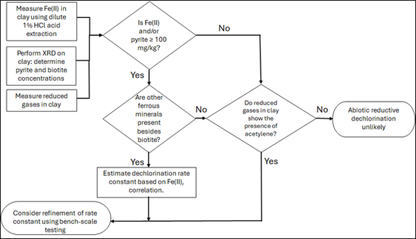
Figure 2: Flowchart diagram of field screening procedures
The recommended approach builds upon the methodology and findings of a recent study[1], emphasizing field-based and analytical techniques to quantify abiotic first-order reductive dechlorination rate constants for PCE and TCE in clayey soils under anoxic conditions. Key components of this evaluation are listed below:
- Zone Identification: The focus of the investigation should be to delineate clayey zones adjacent to hydraulically conductive zones.
- Ferrous Mineral Quantification: Assess ferrous mineral context in clay via 1% HCl extraction at ambient temperature over a 10-minute interval.
- Mineralogical Characterization: Conduct XRD analysis with the specific intent of identifying the presence of pyrite and biotite.
- Reduced Gas Analysis: Measurement of reduced gases such as acetylene, ethene, and ethane concentrations in clay samples. Gas-tight sampling devices (e.g., En Core® soil samplers by En Novative Technologies, Inc.) should be used to ensure sample integrity during collection and transport.
Clay samples should be collected within a few centimeters of the high-permeability interface, with optional additional sampling further inward. For mineralogical analysis, a defined interval may be collected and subsequently subsampled. To preserve sample integrity, exposure to air should be minimized during collection, transport, and handling. Homogenization should occur within an anaerobic chamber, and if subsamples are required for external analysis, they must be shipped in gas-tight, anaerobic containers.
Estimation of the abiotic reductive first-order rate constant for PCE and TCE is based on the “reactive” ferrous content in the clay. Reactive ferrous content (Fe(II)r) is estimated as shown in Equation 1:
- Equation 1: Fe(II)r = DA + XRDpyr - XRDbiotite
where DA is the ferrous content from the dilute acid (1% HCl) extraction, XRDpyr is the pyrite content from XRD analysis, and XRDbiotite is the biotite content from XRD analysis[1].
Abiotic dechlorination is unlikely to contribute to mitigating contaminant back-diffusion when reactive ferrous iron (Fe(II)r) concentrations are below 100 mg/kg (Figure 1). For Fe(II)r above 100 mg/kg, the first-order rate constant for PCE and TCE reductive dechlorination can be estimated using the correlation shown in Figure 1[5][7]. The rate constant exhibits a strong positive correlation with the logarithm of reactive Fe(II) content (Pearson’s r = 0.82), with a slope of 4.7 × 10⁻⁸ L g⁻¹ d⁻¹ (log mg kg⁻¹)⁻¹.
Figure 2 presents a decision flowchart designed to evaluate the significance and extent of abiotic reductive dechlorination. By applying Equation 1 to the dilute acid extractable Fe(II) plus measured mineral species data from clay samples, the reactive ferrous iron content (Fe(II)r) can be quantified, enabling a streamlined assessment of the extent to which abiotic processes are contributing to the mitigation of contaminant back-diffusion.
If Fe(II)r is ≥ 100 mg/kg, a first-order dechlorination rate constant can be estimated and subsequently used within a contaminant fate and transport model. However, if acetylene is detected in the clay, even with Fe(II)r less than 100 mg/kg, then bench-scale testing using methods similar to those described in a recent study[1] is recommended, as such results would likely be inconsistent with those shown in Figure 1, suggesting some other mechanism might be involved, or that the system mineralogy might be more complex than anticipated. Even if Fe(II)r ≥ 100 mg/kg, confirmatory bench-scale testing may be conducted for additional verification and to refine estimation of the abiotic dechlorination rate constant.
Summary and Recommendations
The approach outlined above is intended to serve as a generalized guide for practitioners and site managers to cost-effectively determine the extent to which beneficial abiotic reductive dechlorination reactions are likely occurring in low permeability (e.g., clayey) zones. This approach may be contraindicated if co-contaminants are present. It is currently unclear whether other classes of potentially reactive chemicals, such as trinitrotoluene (TNT) or chlorinated ethanes, could interact competitively with PCE and TCE.
In addition, it remains unclear how other classes of compounds such as per- and polyfluoroalkyl substances (PFAS) may interact or sorb with ferrous minerals and potentially inhibit abiotic dechlorination reactions. Coupling these recommended activities with conventional site investigation tasks would provide an opportunity to perform many of the up-front screening activities with minimal additional project costs. It is important to note that the guidance proposed herein pertains to particularly low permeability media. Sites with complex or varying lithology, where the mineralogy and/or redox conditions may vary, might require evaluation of multiple samples to provide appropriate site-wide information.
References
- ^ 1.0 1.1 1.2 1.3 1.4 Schaefer, C.E., Tran, D., Nguyen, D., Latta, D.E., Werth, C.J., 2025. Evaluating Mineral and In Situ Indicators of Abiotic Dechlorination in Clayey Soils. Groundwater Monitoring and Remediation, 45(2), pp. 31-39. doi: 10.1111/gwmr.12709
- ^ Falta, R., and Wang, W., 2017. A semi-analytical method for simulating matrix diffusion in numerical transport models. Journal of Contaminant Hydrology, 197, pp. 39-49. doi: 10.1016/j.jconhyd.2016.12.007 Open Access Manuscript
- ^ Kulkarni, P.R., Adamson, D.T., Popovic, J., Newell, C.J., 2022. Modeling a well-charactized perfluorooctane sulfate (PFOS) source and plume using the REMChlor-MD model to account for matrix diffusion. Journal of Contaminant Hydrology, 247, Article 103986. doi: 10.1016/j.jconhyd.2022.103986 Open Access Manuscript
- ^ Schaefer, C.E., Ho, P., Berns, E., Werth, C., 2021. Abiotic dechlorination in the presence of ferrous minerals. Journal of Contaminant Hydrology, 241, 103839. doi: 10.1016/j.jconhyd.2021.103839 Open Access Manuscript
- ^ 5.0 5.1 Schaefer, C.E., Ho, P., Berns, E., Werth, C., 2018. Mechanisms for abiotic dechlorination of trichloroethene by ferrous minerals under oxic and anoxic conditions in natural sediments. Environmental Science and Technology, 52(23), pp.13747-13755. doi: 10.1021/acs.est.8b04108
- ^ Schaefer, C.E., Ho., Gurr, C., Berns, E., Werth, C., 2017. Abiotic dechlorination of chlorinated ethenes in natural clayey soils: impacts of mineralogy and temperature. Journal of Contaminant Hydrology, 206, pp. 10-17. doi: 10.1016/j.jconhyd.2017.09.007 Open Access Manuscript
- ^ Borden, R.C., Cha, K.Y., 2021. Evaluating the impact of back diffusion on groundwater cleanup time. Journal of Contaminant Hydrology, 243, Article 103889. doi: 10.1016/j.jconhyd.2021 Open Access Manuscript
See Also

