|
|
| Line 1: |
Line 1: |
| − | ==PFAS Soil Remediation Technologies== | + | ==Estimating PCE/TCE Abiotic First-Order Reductive Dechlorination Rate Constants in Clayey Soils Under Anoxic Conditions== |
| − | [[Perfluoroalkyl and Polyfluoroalkyl Substances (PFAS)]] are mobile in the subsurface and highly resistant to natural degradation processes, therefore soil source areas can be ongoing sources of groundwater contamination. The United States Environmental Protection Agency (US EPA) has not promulgated soil standards for any PFAS, although a handful of states have for select compounds. Soil standards issued for protection of groundwater are in the single digit part per billion range, which is a very low threshold for soil impacts. Well developed soil treatment technologies are limited to capping, excavation with incineration or disposal, and soil stabilization with sorptive amendments. At present, no in situ destructive soil treatment technologies have been demonstrated.
| + | The U.S. Department of Defense (DoD) faces many challenges in restoring aquifers at contaminated sites, often due to back-diffusion of tetrachloroethene (PCE) and trichloroethene (TCE) from low-permeability clay zones. The uptake, storage, and subsequent long-term release of these dissolved contaminants from clays are key processes in understanding the longevity, intensity, and risks associated with many persistent chlorinated ethene groundwater plumes. Although naturally occurring abiotic and biotic dechlorination processes in clays may reduce stored contaminant mass and significantly aid natural attenuation, no standardized field method currently exists to verify or quantify these reactions. It is critical to remediation design efforts to demonstrate and validate a cost-effective in situ approach for assessing these dechlorination processes using first-order rate constants. An approach was developed and applied across eight DoD sites to support Remedial Project Managers (RPMs) and regulators in evaluating natural attenuation potential in clay-rich environments. |
| | <div style="float:right;margin:0 0 2em 2em;">__TOC__</div> | | <div style="float:right;margin:0 0 2em 2em;">__TOC__</div> |
| | | | |
| | '''Related Article(s):''' | | '''Related Article(s):''' |
| | | | |
| − | * [[Perfluoroalkyl and Polyfluoroalkyl Substances (PFAS)]] | + | *[[Monitored Natural Attenuation (MNA)]] |
| − | * [[PFAS Transport and Fate]] | + | *[[Monitored Natural Attenuation (MNA) of Chlorinated Solvents]] |
| − | * [[PFAS Sources]] | + | *[[Monitored Natural Attenuation - Transitioning from Active Remedies]] |
| | + | *[[Matrix Diffusion]] |
| | + | *[[REMChlor - MD]] |
| | | | |
| − | '''Contributor(s):''' [[Jim Hatton]] and [[Bill DiGuiseppi]] | + | '''Contributors:''' Dani Tran, Dr. Charles Schaefer, Dr. Charles Werth |
| | | | |
| − | '''Key Resource(s):''' | + | '''Key Resource:''' |
| | + | *Schaefer, C.E, Tran, D., Nguyen, D., Latta, D.E., Werth, C.J., 2025. Evaluating Mineral and In Situ Indicators of Abiotic Dechlorination in Clayey Soils<ref name="SchaeferEtAl2025"/> |
| | | | |
| − | *[https://pfas-1.itrcweb.org/12-treatment-technologies/ ITRC Fact Sheet: Treatment Technologies, PFAS – Per- and Polyfluoroalkyl Substances]<ref name="ITRC2020">Interstate Technology and Regulatory Council (ITRC), 2020. PFAS Technical and Regulatory Guidance Document and Fact Sheets, PFAS-1. PFAS Team, Washington, DC. [https://pfas-1.itrcweb.org/ Website] [[Media: ITRC_PFAS-1.pdf | Report.pdf]]</ref>.
| + | ==Introduction== |
| − | *Persistence of Perfluoroalkyl Acid Precursors in AFFF-Impacted Groundwater and Soil<ref name="Houtz2013">Houtz, E.F., Higgins, C.P., Field, J.A., and Sedlak, D.L., 2013. Persistence of Perfluoroalkyl Acid Precursors in AFFF-Impacted Groundwater and Soil. Environmental Science and Technology, 47(15), pp. 8187−8195. [https://doi.org/10.1021/es4018877 DOI: 10.1021/es4018877]</ref>.
| + | Cost-effective methods are needed to verify the occurrence of natural dechlorination processes and quantify their dechlorination rates in clays under ambient in situ conditions in order to reliably predict their long-term influence on plume longevity and mass discharge. However, accurately determining these rates is challenging due to slow reaction kinetics, the transient nature of transformation products, and the interplay of biotic and abiotic mechanisms within the clay matrix or at clay-sand interfaces. Tools capable of quantifying these reactions and assessing their role in mitigating plume persistence would be a significant aid for long-term site management. |
| | | | |
| − | ==Introduction==
| + | For reductive abiotic dechlorination under anoxic conditions, a 1% hydrochloric acid (HCl) extraction of a sample of native clay coupled with X-ray diffraction (XRD) data can be used as a screening level tool to estimate reductive dechlorination rate constants. These rate constants can be inserted into fate and transport models such as [[REMChlor - MD]]<ref>Falta, R., and Wang, W., 2017. A semi-analytical method for simulating matrix diffusion in numerical transport models. Journal of Contaminant Hydrology, 197, pp. 39-49. [https://doi.org/10.1016/j.jconhyd.2016.12.007 doi: 10.1016/j.jconhyd.2016.12.007] [[Media: FaltaWang2017.pdf | Open Access Manuscript]]</ref><ref>Kulkarni, P.R., Adamson, D.T., Popovic, J., Newell, C.J., 2022. Modeling a well-charactized perfluorooctane sulfate (PFOS) source and plume using the REMChlor-MD model to account for matrix diffusion. Journal of Contaminant Hydrology, 247, Article 103986. [https://doi.org/10.1016/j.jconhyd.2022.103986 doi: 10.1016/j.jconhyd.2022.103986] [[Media: KulkarniEtAl2022.pdf | Open Access Manuscript]]</ref> to quantify abiotic dechlorination impacts within clay aquitards on chlorinated solvent plumes. Thus, determination of the abiotic reductive dechlorination rate constant for a particular clayey soil can be readily utilized to provide a more accurate assessment of aquifer cleanup timeframes for groundwater plumes that are being sustained by contaminant back-diffusion. |
| − | PFAS are a class of highly fluorinated compounds including perfluorooctane sulfonate (PFOS), perfluorooctanoic acid (PFOA), and many other compounds with a variety of industrial and consumer uses. These compounds are often highly resistant to treatment<ref name="Kissa2001">Kissa, Erik, 2001. Fluorinated Surfactants and Repellents: Second Edition. Surfactant Science Series, Volume 97. Marcel Dekker, Inc., CRC Press, New York. 640 pages. ISBN 978-0824704728</ref> and the more mobile compounds are often problematic in groundwater systems<ref name="Backe2013">Backe, W.J., Day, T.C., and Field, J.A., 2013. Zwitterionic, Cationic, and Anionic Fluorinated Chemicals in Aqueous Film Forming Foam Formulations and Groundwater from U.S. Military Bases by Nonaqueous Large-Volume Injection HPLC-MS/MS. Environmental Science and Technology, 47(10), pp. 5226-5234. [https://doi.org/10.1021/es3034999 DOI: 10.1021/es3034999]</ref>. The US EPA has published lifetime drinking water health advisories for the combined concentration of 70 nanograms per liter (ng/L) for two common and recalcitrant PFAS: PFOS, a perfluoroalkyl sulfonic acid (PFSA), and PFOA, a perfluoroalkyl carboxylic acid (PFCA)<ref name="EPApfos2016">US Environmental Protection Agency (EPA), 2016. Drinking Water Health Advisory for Perfluorooctane Sulfonate (PFOS), EPA 822-R-16-004. Office of Water, Health and Ecological Criteria Division, Washington, DC. [https://www.epa.gov/sites/production/files/2016-05/documents/pfos_health_advisory_final-plain.pdf Free download from US EPA] [[Media: EPA822-R-16-004.pdf | Report.pdf]]</ref><ref name="EPApfoa2016">US Environmental Protection Agency (EPA), 2016. Drinking Water Health Advisory for Perfluorooctanoic Acid (PFOA), EPA 822-R-16-005. Office of Water, Health and Ecological Criteria Division, Washington, DC. [https://www.epa.gov/sites/production/files/2016-05/documents/pfoa_health_advisory_final-plain.pdf Free download from US EPA] [[Media: EPA822-R-16-005.pdf | Report]]</ref>.(See [[Perfluoroalkyl and Polyfluoroalkyl Substances (PFAS)]] for nomenclature.)
| + | |
| | + | ==Recommended Approach== |
| | + | [[File: TranFig1.png | thumb | 500 px | Figure 1: First-order rate constants for abiotic reductive dechlorination of TCE under anaerobic conditions. Circles are data from Schaefer ''et al.'', 2021<ref>Schaefer, C.E., Ho, P., Berns, E., Werth, C., 2021. Abiotic dechlorination in the presence of ferrous minerals. Journal of Contaminant Hydrology, 241, 103839. [https://doi.org/10.1016/j.jconhyd.2021.103839 doi: 10.1016/j.jconhyd.2021.103839] [[Media: SchaeferEtAl2021.pdf | Open Access Manuscript]]</ref>, filled squares from Schaefer ''et al.'', 2018<ref name="SchaeferEtAl2018"/>, and Schaefer ''et al.'', 2017<ref>Schaefer, C.E., Ho., Gurr, C., Berns, E., Werth, C., 2017. Abiotic dechlorination of chlorinated ethenes in natural clayey soils: impacts of mineralogy and temperature. Journal of Contaminant Hydrology, 206, pp. 10-17. [https://doi.org/10.1016/j.jconhyd.2017.09.007 doi: 10.1016/j.jconhyd.2017.09.007] [[Media: SchaeferEtAl2017.pdf | Open Access Manuscript]]</ref>, and open squares from Schaefer ''et al.'', 2025<ref name="SchaeferEtAl2025"/>. ]] |
| | + | [[File: TranFig2.png | thumb | 600 px | Figure 2: Flowchart diagram of field screening procedures]] |
| | + | The recommended approach builds upon the methodology and findings of a recent study<ref name="SchaeferEtAl2025">Schaefer, C.E., Tran, D., Nguyen, D., Latta, D.E., Werth, C.J., 2025. Evaluating Mineral and In Situ Indicators of Abiotic Dechlorination in Clayey Soils. Groundwater Monitoring and Remediation, 45(2), pp. 31-39. [https://doi.org/10.1111/gwmr.12709 doi: 10.1111/gwmr.12709]</ref>, emphasizing field-based and analytical techniques to quantify abiotic first-order reductive dechlorination rate constants for PCE and TCE in clayey soils under anoxic conditions. Key components of this evaluation are listed below: |
| | + | #<u>Zone Identification:</u> The focus of the investigation should be to delineate clayey zones adjacent to hydraulically conductive zones. |
| | + | #<u>Ferrous Mineral Quantification:</u> Assess ferrous mineral context in clay via 1% HCl extraction at ambient temperature over a 10-minute interval. |
| | + | #<u>Mineralogical Characterization:</u> Conduct XRD analysis with the specific intent of identifying the presence of pyrite and biotite. |
| | + | #<u>Reduced Gas Analysis:</u> Measurement of reduced gases such as acetylene, ethene, and ethane concentrations in clay samples. Gas-tight sampling devices (e.g., En Core® soil samplers by En Novative Technologies, Inc.) should be used to ensure sample integrity during collection and transport. |
| | + | |
| | + | Clay samples should be collected within a few centimeters of the high-permeability interface, with optional additional sampling further inward. For mineralogical analysis, a defined interval may be collected and subsequently subsampled. To preserve sample integrity, exposure to air should be minimized during collection, transport, and handling. Homogenization should occur within an anaerobic chamber, and if subsamples are required for external analysis, they must be shipped in gas-tight, anaerobic containers. |
| | | | |
| − | While many of the earliest sites where these compounds were detected in groundwater were manufacturing sites, some recent detections have been attributed to fire training activities associated with aqueous film-forming foams (AFFF). AFFF is the US Department of Defense (DoD) designation for Class B firefighting foam containing PFAS, which is required for fighting fires involving petroleum liquids. Fire training areas and other source areas where AFFF was released at the surface have the potential to be ongoing sources of groundwater contamination<ref name="Houtz2013"/>. (See also [[PFAS Sources]].)
| + | Estimation of the abiotic reductive first-order rate constant for PCE and TCE is based on the “reactive” ferrous content in the clay. Reactive ferrous content (Fe(II)<sub>r</sub>) is estimated as shown in Equation 1: |
| | | | |
| − | No national soil cleanup standards have been promulgated by the US EPA, although Regional Screening Levels (RSLs) have been calculated and published for perfluorobutane sulfonate (PFBS)<ref name="EPA2020">US Environmental Protection Agency (EPA), 2020. Regional Screening Levels (RSLs) – User's Guide. Washington, DC. [https://www.epa.gov/risk/regional-screening-levels-rsls-users-guide Website]</ref> and data are available to calculate RSLs for PFOA and PFOS<ref name="ITRCwNs2020">Interstate Technology Regulatory Council (ITRC), 2020. PFAS Water and Soil Values Table. PFAS – Per- and Polyfluoroalkyl Substances: PFAS Fact Sheets. [https://pfas-1.itrcweb.org/wp-content/uploads/2020/12/ITRCPFASWaterandSoilValuesTables_NOV-2020-FINAL.xlsx Free download.] [[Media: ITRCPFASWaterandSoilTables2020.xlsx | 2020 Water and Soil Tables (excel file)]]</ref>. Several states have promulgated standards<ref name="AKDEC2020">Alaska Department of Environmental Conservation (AK DEC), 2020. 18 AAC 75, Oil and Other Hazardous Substances Pollution Control. Anchorage, AK. [https://dec.alaska.gov/media/1055/18-aac-75.pdf Free download.] [[Media: AKDEC2020_18aac75.pdf | Report.pdf]]</ref> or screening levels<ref name="MEDEP2018">Maine Department of Environmental Protection (ME DEP), 2018. Maine Remedial Action Guidelines (RAGs) for Sites Contaminated with Hazardous Substances. Augusta, ME. [https://www.maine.gov/dep/spills/publications/guidance/rags/ME-Remedial-Action-Guidelines-10-19-18cc.pdf Free download.] [[Media: MEDEP2018.pdf | Report.pdf]]</ref><ref name="EGLE2020">Michigan Department of Environment, Great Lakes, and Energy (EGLE), 2020. Cleanup Criteria Requirements for Response Activity (Formerly the Part 201 Generic Cleanup Criteria and Screening Levels). Remediation and Redevelopment Division, Lansing, MI. [https://www.michigan.gov/egle/0,9429,7-135-3311_4109_9846-251790--,00.html Website]</ref><ref name="NEDEE2018">Nebraska Department of Energy and Environment (NE DEE), 2018. Voluntary Cleanup Program Remedial Goals, Table A-1: Groundwater and Soil Remediation Goals. Lincoln, NE. [http://www.deq.state.ne.us/Publica.nsf/xsp/.ibmmodres/domino/OpenAttachment/Publica.nsf/D243C2B56E34EA8486256F2700698997/Body/Attach%202-6%20Table%20A-1%20VCP%20LUT%20Sept%202018.pdf Free download.] [[Media: NDEE2018.pdf | Report.pdf]]</ref><ref name="NCDEQ2020">North Carolina Department of Environmental Quality (NC DEQ), 2020. Preliminary Soil Remediation Goals (PSRG) Table. Raleigh, NC. [https://files.nc.gov/ncdeq/risk-based-remediation/1.Combined-Notes-PSRGs.pdf Free download.] [[Media: NCDEQ2020.pdf | Report.pdf]]</ref><ref name="TCEQ2021">Texas Commission on Environmental Quality (TCEQ), 2021. Texas Risk Reduction Program (TRRP), Tier 1 Protective Concentration Levels (PCL) Tables. [http://www.tceq.texas.gov/assets/public/remediation/trrp/2021PCL%20Tables.xlsx Free Download.] [[Media: TRRP2021PCLTables.xlsx | 2021 PCL Tables (excel file)]]</ref> for soil concentrations protective of groundwater, which are several orders of magnitude lower than direct dermal exposure guidelines. These single-digit part per billion criteria will likely drive remedial actions in PFAS source areas in the future. At present, the lack of federally promulgated standards and uncertainty about future standards causes temporary stockpiling of PFAS-impacted soils on sites with soil generated from construction or investigation activities.
| + | ::'''Equation 1:''' <big>''Fe(II)<sub><small>r</small></sub> = DA + XRD<sub><small>pyr</small></sub> - XRD<sub><small>biotite</small></sub>''</big> |
| | | | |
| − | ==Soil Treatment==
| + | where ''DA'' is the ferrous content from the dilute acid (1% HCl) extraction, ''XRD<sub><small>pyr</small></sub>'' is the pyrite content from XRD analysis, and ''XRD<sub><small>biotite</small></sub>'' is the biotite content from XRD analysis<ref name="SchaeferEtAl2025"/>. |
| − | [[File: DiGuiseppi1w2Fig1.PNG |thumb|600px| Figure 1. A full scale PFAS-impacted soil stabilization project at a military base in Australia. Image courtesy of RemBind™.]]
| |
| − | Addressing recalcitrant contaminants in soil has traditionally been done through containment/capping or excavation and off-site disposal or treatment. Containment/capping may be an acceptable solution for PFAS in some locations. However, containment/capping is not considered ideal given the history of releases from engineered landfills and restrictions on use of land containing capped soils. Innovative treatment approaches for PFAS include stabilization with amendments and thermal treatment.
| |
| | | | |
| − | ===Excavation and Disposal===
| + | Abiotic dechlorination is unlikely to contribute to mitigating contaminant back-diffusion when reactive ferrous iron (Fe(II)<sub><small>r</small></sub>) concentrations are below 100 mg/kg (Figure 1). For Fe(II)<sub><small>r</small></sub> above 100 mg/kg, the first-order rate constant for PCE and TCE reductive dechlorination can be estimated using the correlation shown in Figure 1<ref name="SchaeferEtAl2018">Schaefer, C.E., Ho, P., Berns, E., Werth, C., 2018. Mechanisms for abiotic dechlorination of trichloroethene by ferrous minerals under oxic and anoxic conditions in natural sediments. Environmental Science and Technology, 52(23), pp.13747-13755. [https://doi.org/10.1021/acs.est.8b04108 doi: 10.1021/acs.est.8b04108]</ref><ref>Borden, R.C., Cha, K.Y., 2021. Evaluating the impact of back diffusion on groundwater cleanup time. Journal of Contaminant Hydrology, 243, Article 103889. [https://doi.org/10.1016/j.jconhyd.2021.103889 doi: 10.1016/j.jconhyd.2021] [[Media: BordenCha2021.pdf | Open Access Manuscript]]</ref>. The rate constant exhibits a strong positive correlation with the logarithm of reactive Fe(II) content (Pearson’s ''r'' = 0.82), with a slope of 4.7 × 10⁻⁸ L g⁻¹ d⁻¹ (log mg kg⁻¹)⁻¹. |
| − | Excavation and off-site disposal or treatment of PFAS-impacted soils is the only well-developed treatment technology option and may be acceptable for small quantities of soil, such as those generated during characterization activities (i.e., investigation derived waste, IDW). Disposal in non-hazardous landfills is allowable in most states. However, some landfill operators are choosing to restrict acceptance of PFAS-containing waste and soils as a protection against future liability. In addition, the US EPA and some states are considering or have designated PFOA and PFOS as hazardous substances, which would reduce the number of facilities where disposal of PFAS-contaminated soil would be allowed<ref name="EPA2019">US Environmental Protection Agency (EPA), 2019. EPA’s Per- and Polyfluoroalkyl Substances (PFAS) Action Plan: EPA 823R18004. Washington, DC. [https://www.epa.gov/pfas/epas-pfas-action-plan Website] [[Media: EPA823R18004.pdf | Report.pdf]] [[Media: EPA100K20002.pdf | 2020 Update]]</ref>. Treatment of excavated soils is commonly performed using incineration or other high temperature thermal methods<ref name="ITRC2020"/>. Recent negative publicity regarding incomplete combustion of PFAS in incinerators<ref name="Hogue2020">Cheryl Hogue, 2020. Incineration may spread, not break down PFAS. Chemical and Engineering News, American Chemical Society. [https://cen.acs.org/environment/persistent-pollutants/Incincerators-spread-break-down-PFAS/98/web/2020/04 Website] [[Media: Hogue2020.pdf | Report.pdf]]</ref> has caused some states to ban PFAS incineration<ref name="NYSS2020">New York State Senate, 2020. An ACT prohibiting the incineration of aqueous film-forming foam containing perfluoroalkyl and polyfluoroalkyl substances in certain cities. [https://www.nysenate.gov/legislation/bills/2019/s7880/amendment/b Website] [[Media: NYsenate2020.pdf | Report.pdf]]</ref>.
| |
| | | | |
| − | ===Stabilization===
| + | Figure 2 presents a decision flowchart designed to evaluate the significance and extent of abiotic reductive dechlorination. By applying Equation 1 to the dilute acid extractable Fe(II) plus measured mineral species data from clay samples, the reactive ferrous iron content (Fe(II)<sub><small>r</small></sub>) can be quantified, enabling a streamlined assessment of the extent to which abiotic processes are contributing to the mitigation of contaminant back-diffusion. |
| − | [[File:DiGuiseppi1w2Fig2.PNG|thumb|600px| Figure 2. A mobile infrared thermal treatment unit for PFAS-impacted soils<ref name="DiGuiseppi2019"/>.]]
| |
| − | Various amendments have been manufactured to sorb PFAS to reduce leaching from soil. Although this is a non-destructive approach, stabilization can reduce mass flux from a source area or allow soils to be placed in landfills with reduced potential for leaching. Amendments sorb PFAS through hydrophobic and electrostatic interactions and are applied to soil through ''in situ'' soil mixing or ''ex situ'' stabilization (Figure 1). Effectiveness of amendments varies depending on site conditions, PFAS types present, and mixing conditions<ref name="ITRCwNs2020"/>. Good results have been observed in bench and field scale tests with a variety of cationic clays (natural or chemically modified) and zeolites<ref name="OchoaHerrera2008">Ochoa-Herrera, V., and Sierra-Alvarez, R., 2008. Removal of perfluorinated surfactants by sorption onto granular activated carbon, zeolites and sludge. Chemosphere, 72(10), pp. 1588-1593. [https://doi.org/10.1016/j.chemosphere.2008.04.029 DOI: 10.1016/j.chemosphere.2008.04.029]</ref><ref name="Rattanaoudom2012">Rattanaoudom, R., Visvanathan, C., and Boontanon, S.K., 2012. Removal of Concentrated PFOS and PFOA in Synthetic Industrial Wastewater by Powder Activated Carbon and Hydrotalcite. Journal of Water Sustainability, 2(4), pp. 245-248. [http://www.jwsponline.com/uploadpic/Magazine/pp%20245-258.pdf Open access article.] [[Media: Rattanaoudom2012.pdf | Report.pdf]]</ref><ref name="Ziltek2017">Ziltek, 2017. RemBind: Frequently Asked Questions. [https://static1.squarespace.com/static/5c5503db4d546e22f6d2feb2/t/5c733787f9619ae6c84674c9/1551054727451/RemBind+FAQs.pdf Free download] [[Media: RemBind2017.pdf | Report.pdf]]</ref>. Bench-scale tests have shown that activated carbon sorbents reduce leachability of PFAS from soils<ref name="Du2014">Du, Z., Deng, S., Bei, Y., Huang, Q., Wang, B., Huang, J. and Yu, G., 2014. Adsorption behavior and mechanism of perfluorinated compounds on various adsorbents – A review. Journal of Hazardous Materials, 274, pp. 443-454. [https://doi.org/10.1016/j.jhazmat.2014.04.038 DOI: 10.1016/j.jhazmat.2014.04.038]</ref><ref name="Yu2009">Yu, Q., Zhang, R., Deng, S., Huang, J. and Yu, G., 2009. Sorption of perfluorooctane sulfonate and perfluorooctanoate on activated carbons and resin: Kinetic and isotherm study. Water Research, 43(4), pp. 1150-1158. [https://doi.org/10.1016/j.watres.2008.12.001 DOI: 10.1016/j.watres.2008.12.001]</ref><ref name="Szabo2017">Szabo, J., Hall, J., Magnuson, M., Panguluri, S., and Meiners, G., 2017. Treatment of Perfluorinated Alkyl Substances in Wash Water Using Granular Activated Carbon and Mixed Media, EPA/600/R-17/175. US Environmental Protection Agency (EPA), Washington, DC. [https://cfpub.epa.gov/si/si_public_record_report.cfm?Lab=NHSRC&direntryid=337098 Website] [[Media: EPA600R17175.PDF | Report.pdf]]</ref>. A commercial product developed in Australia ([https://rembind.com/ RemBind™]) combines the cation exchange binding capability of clays, the hydrophobic sorption and [[Wikipedia: Van der Waals force | van der Waals]] attraction of organic material, and the electrostatic interactions of aluminum hydroxide to create a highly effective soil stabilizer. This material has been mixed into soil at 1 to 5% ratio by weight in ''ex situ'' applications and been demonstrated to reduce leachability by greater than 99 percent<ref name="Nolan2015">Nolan, A., Anderson, P., McKay, D., Cartwright, L., and McLean, C., 2015. Treatment of PFCs in Soils, Sediments and Water, WC35. Program and Proceedings, CleanUp Conference 2015. Cooperative Research Centre for Contamination Assessment and Remediation of the Environment (CRC Care), Melbourne, Australia. pp. 374-375. [https://www.crccare.com/files/dmfile/CLEANUP_2015_PROCEEDINGS-web.pdf Free download] [[Media: CRCCare2015.pdf | Report.pdf]]</ref>.
| |
| | | | |
| − | ===Thermal Treatment===
| + | If Fe(II)r is ≥ 100 mg/kg, a first-order dechlorination rate constant can be estimated and subsequently used within a contaminant fate and transport model. However, if acetylene is detected in the clay, even with Fe(II)r less than 100 mg/kg, then bench-scale testing using methods similar to those described in a recent study<ref name="SchaeferEtAl2025"/> is recommended, as such results would likely be inconsistent with those shown in Figure 1, suggesting some other mechanism might be involved, or that the system mineralogy might be more complex than anticipated. Even if Fe(II)r ≥ 100 mg/kg, confirmatory bench-scale testing may be conducted for additional verification and to refine estimation of the abiotic dechlorination rate constant. |
| − | [[File:DiGuiseppi1w2Fig3.PNG|thumb|600px| Figure 3. A full scale PFAS-impacted soil washing plant at a military base in Australia<ref name="Grimison2020"/>.]]
| |
| − | ''Incineration:'' Incineration is a well-developed technology for organics destruction, including PFAS-impacted soils. Incineration is generally defined as high temperature (>1,100°C) thermal destruction of waste, and PFAS are thought to mineralize at high temperatures. Generally, incinerators treat off-gasses by thermal oxidation with temperatures as high as 1,400°C, and vaporized combustion products can be captured using condensation and wet scrubbing<ref name="ITRCwNs2020"/>. Some regulatory officials have expressed concern about possible PFAS emissions in off-gas from these incinerators, and the authors are not aware of any published evidence demonstrating complete mineralization of multiple PFAS in incinerators at the time of this posting. In general, incineration is designed to provide “5 nines of destruction” – destruction of 99.999% of the contaminants, although incinerators are not designed to specifically treat PFAS to this standard. In the absence of approved industry standard test methods, the US EPA is developing off-gas/stack testing procedures capable of detecting PFAS at the levels considered to be harmful<ref name="EPA2018">US Environmental Protection Agency (EPA), 2018. PFAS Research and Development, Community Engagement in Fayetteville, North Carolina. [https://www.epa.gov/pfas/pfas-community-engagement-north-carolina-meeting-materials Website] [[Media: EPAFayetteville2018.pdf | Report.pdf]]</ref>.
| |
| | | | |
| − | ''Thermal Desorption:'' Thermal Desorption of PFAS from soil has been demonstrated at the field scale in Australia and the US (Alaska)<ref name="Nolan2015"/> using a rotary kiln operating at temperatures in the range of 900°C or less with treatment times of 10-15 minutes<ref name="Burke2015">Burke, Jill, 2019. Fairbanks incinerator shows promise for cleaning toxic soil. Channel 2-KTUU, October 8. [https://www.ktuu.com/content/news/Fairbanks-incinerator-shows-promise-for-cleaning-toxic-soil-562593631.html Website]</ref>. At these temperatures, some PFAS are mineralized, releasing fluorine that must be captured in off-gas treatment systems. Some PFAS would not be destroyed at these temperatures and therefore must be captured in off-gas treatment systems. Several bench-scale tests have been performed that have narrowed down the optimal temperature for desorption to between 350°C and 400°C<ref name="Hatton2019">Hatton, J., Dasu, K., Richter, R., Fitzpatrick, T., and Higgins, C., 2019. Field Demonstration of Infrared Thermal Treatment of PFAS-impacted Soils from Subsurface Investigations. Strategic Environmental Research and Development Program (SERDP), Project ER18-1603, Alexandria, VA. [https://www.serdp-estcp.org/Program-Areas/Environmental-Restoration/ER18-1603 Website] [[Media: SERDP ER18-1603.pdf | Report.pdf]]</ref><ref name="DiGuiseppi2019">DiGuiseppi, W., Richter, R., and Riggle, M., 2019. Low Temperature Desorption of Per- and Polyfluoroalkyl Substances. The Military Engineer, 111(719), pp. 52-53. Society of American Military Engineers, Washington, DC. [http://online.fliphtml5.com/fedq/sdoo/#p=54 Open access article.] [[Media: DiGuiseppi2019.pdf | Report.pdf]]</ref>. A US Department of Defense (DoD) Strategic Environmental Research and Development Program (SERDP) field-scale demonstration was performed in Oregon, where thermal desorption was conducted at 400°C over several days, and the PFAS were captured on vapor-phase activated carbon and incinerated<ref name="Hatton2019"/>. An ''in situ'' thermal desorption project has been funded under the US DoD’s Environmental Security Technology Certification Program (ESTCP) to demonstrate that vadose zone soil can be heated to the requisite 350°C and held there for the appropriate length of time to desorb and capture PFAS from soil source areas<ref name="Iery2020">Iery, R., 2020. In Situ Thermal Treatment of PFAS in the Vadose Zone. US Department of Defense, Environmental Security Technology Certification Program (ESTCP), Project ER20-5250. [https://www.serdp-estcp.org/Program-Areas/Environmental-Restoration/Contaminated-Groundwater/Emerging-Issues/ER20-5250 Website]</ref>.
| + | ==Summary and Recommendations== |
| | + | The approach outlined above is intended to serve as a generalized guide for practitioners and site managers to cost-effectively determine the extent to which beneficial abiotic reductive dechlorination reactions are likely occurring in low permeability (e.g., clayey) zones. This approach may be contraindicated if co-contaminants are present. It is currently unclear whether other classes of potentially reactive chemicals, such as trinitrotoluene (TNT) or chlorinated ethanes, could interact competitively with PCE and TCE. |
| | | | |
| − | ===Soil Washing===
| + | In addition, it remains unclear how other classes of compounds such as per- and polyfluoroalkyl substances (PFAS) may interact or sorb with ferrous minerals and potentially inhibit abiotic dechlorination reactions. Coupling these recommended activities with conventional site investigation tasks would provide an opportunity to perform many of the up-front screening activities with minimal additional project costs. It is important to note that the guidance proposed herein pertains to particularly low permeability media. Sites with complex or varying lithology, where the mineralogy and/or redox conditions may vary, might require evaluation of multiple samples to provide appropriate site-wide information. |
| − | Soil washing has been applied to PFAS in a handful of pilot projects<ref name="Torneman2012">Torneman, N., 2012. Remedial Methods and Strategies for PFCs. Fourth Joint Nordic Meeting on Remediation of Contaminated Sites, NORDROCS 2012, Oslo, Norway. [http://nordrocs.org/wp-content/uploads/2012/09/Session-VI-torsdag-1-Torneman-short-paper.pdf Free download.] [[Media: Torneman2012.pdf | Report.pdf]]</ref><ref name="Toase2018">Toase, D., 2018. Application of enhanced soil washing techniques to PFAS contaminated source zones. Emerging Contaminants Summit 2018, Westminster, Colorado.</ref><ref name="Grimison2018">Grimison, C., Barthelme, S., Nolan, A., Cole, J., Morrell, C., 2018. Integrated Soil and Water System for Treatment of PFAS Impacted Source Areas, 18E138P. Australasian Land and Groundwater Association (ALGA), Sydney, Australia. [https://landandgroundwater.com/media/18E138P_-_Charles_Grimison.pdf Free download.] [[Media: Grimison2018.pdf | Report.pdf]]</ref> and one full-scale implementation in Australia. This approach requires a large-scale engineered plant to handle the various liquid and solid waste streams generated. Soil washing is less suitable for clay-rich soils, where aggregation of the particulates occurs and is difficult to prevent or mitigate. Treatment of the liquid rinse water waste stream is required, which would then rely on conventional water treatment technologies such as granular activated carbon (GAC) or ion exchange. Additionally, in some cases flocculated sludge is generated, which would require treatment or disposal offsite. At present, the only full-scale soil washing demonstration is occurring in Australia, where a vendor has constructed and is operating a 10 million AUD$ treatment plant in anticipation of future treatment of soils generated from remedial actions at Australian Defence installations. Some Australian installations are stockpiling soils due to the lack of cost-effective soil treatment options. According to the vendor, this system generates no solid waste, instead feeding any solids back into the front end of the process for further removal of PFAS<ref name="Grimison2020">Grimison, C., Brookman, I., Hunt, J., and Lucas, J., 2020. Remediation of PFAS-related impacts – ongoing scrutiny and review, Ventia Submission to PFAS Subcommittee of the Joint Standing Committee on Foreign Affairs, Defence and Trade, Australia. [https://www.aph.gov.au/DocumentStore.ashx?id=a209e924-2b7e-4727-bccf-30bef5304bba&subId=691428 Free download.] [[Media: Grimison2020.pdf | Report.pdf]]</ref>.
| |
| | | | |
| − | ==Conclusions==
| + | <br clear="right"/> |
| − | Several well-developed remedial technologies have been applied to address soil contaminated with PFAS. Unfortunately, none of the available techniques are ideal, with some leaving the PFAS-impacted soil in place while reducing leachability, while others result in destruction but require high energy inputs with associated high cost.
| |
| − | <br clear="left" /> | |
| | | | |
| | ==References== | | ==References== |
| − |
| |
| | <references /> | | <references /> |
| | | | |
| | ==See Also== | | ==See Also== |
| | + | *[https://serdp-estcp.mil/projects/details/a7e3f7b5-ed82-4591-adaa-6196ff33dd60 ESTCP Project ER20-5031 – In Situ Verification and Quantification of Naturally Occurring Dechlorination Rates in Clays: Demonstrating Processes that Mitigate Back-Diffusion and Plume Persistence] |
Estimating PCE/TCE Abiotic First-Order Reductive Dechlorination Rate Constants in Clayey Soils Under Anoxic Conditions
The U.S. Department of Defense (DoD) faces many challenges in restoring aquifers at contaminated sites, often due to back-diffusion of tetrachloroethene (PCE) and trichloroethene (TCE) from low-permeability clay zones. The uptake, storage, and subsequent long-term release of these dissolved contaminants from clays are key processes in understanding the longevity, intensity, and risks associated with many persistent chlorinated ethene groundwater plumes. Although naturally occurring abiotic and biotic dechlorination processes in clays may reduce stored contaminant mass and significantly aid natural attenuation, no standardized field method currently exists to verify or quantify these reactions. It is critical to remediation design efforts to demonstrate and validate a cost-effective in situ approach for assessing these dechlorination processes using first-order rate constants. An approach was developed and applied across eight DoD sites to support Remedial Project Managers (RPMs) and regulators in evaluating natural attenuation potential in clay-rich environments.
Related Article(s):
Contributors: Dani Tran, Dr. Charles Schaefer, Dr. Charles Werth
Key Resource:
- Schaefer, C.E, Tran, D., Nguyen, D., Latta, D.E., Werth, C.J., 2025. Evaluating Mineral and In Situ Indicators of Abiotic Dechlorination in Clayey Soils[1]
Introduction
Cost-effective methods are needed to verify the occurrence of natural dechlorination processes and quantify their dechlorination rates in clays under ambient in situ conditions in order to reliably predict their long-term influence on plume longevity and mass discharge. However, accurately determining these rates is challenging due to slow reaction kinetics, the transient nature of transformation products, and the interplay of biotic and abiotic mechanisms within the clay matrix or at clay-sand interfaces. Tools capable of quantifying these reactions and assessing their role in mitigating plume persistence would be a significant aid for long-term site management.
For reductive abiotic dechlorination under anoxic conditions, a 1% hydrochloric acid (HCl) extraction of a sample of native clay coupled with X-ray diffraction (XRD) data can be used as a screening level tool to estimate reductive dechlorination rate constants. These rate constants can be inserted into fate and transport models such as REMChlor - MD[2][3] to quantify abiotic dechlorination impacts within clay aquitards on chlorinated solvent plumes. Thus, determination of the abiotic reductive dechlorination rate constant for a particular clayey soil can be readily utilized to provide a more accurate assessment of aquifer cleanup timeframes for groundwater plumes that are being sustained by contaminant back-diffusion.
Recommended Approach
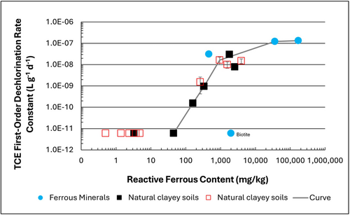
Figure 1: First-order rate constants for abiotic reductive dechlorination of TCE under anaerobic conditions. Circles are data from Schaefer
et al., 2021
[4], filled squares from Schaefer
et al., 2018
[5], and Schaefer
et al., 2017
[6], and open squares from Schaefer
et al., 2025
[1].
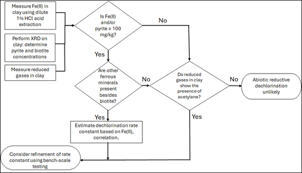
Figure 2: Flowchart diagram of field screening procedures
The recommended approach builds upon the methodology and findings of a recent study[1], emphasizing field-based and analytical techniques to quantify abiotic first-order reductive dechlorination rate constants for PCE and TCE in clayey soils under anoxic conditions. Key components of this evaluation are listed below:
- Zone Identification: The focus of the investigation should be to delineate clayey zones adjacent to hydraulically conductive zones.
- Ferrous Mineral Quantification: Assess ferrous mineral context in clay via 1% HCl extraction at ambient temperature over a 10-minute interval.
- Mineralogical Characterization: Conduct XRD analysis with the specific intent of identifying the presence of pyrite and biotite.
- Reduced Gas Analysis: Measurement of reduced gases such as acetylene, ethene, and ethane concentrations in clay samples. Gas-tight sampling devices (e.g., En Core® soil samplers by En Novative Technologies, Inc.) should be used to ensure sample integrity during collection and transport.
Clay samples should be collected within a few centimeters of the high-permeability interface, with optional additional sampling further inward. For mineralogical analysis, a defined interval may be collected and subsequently subsampled. To preserve sample integrity, exposure to air should be minimized during collection, transport, and handling. Homogenization should occur within an anaerobic chamber, and if subsamples are required for external analysis, they must be shipped in gas-tight, anaerobic containers.
Estimation of the abiotic reductive first-order rate constant for PCE and TCE is based on the “reactive” ferrous content in the clay. Reactive ferrous content (Fe(II)r) is estimated as shown in Equation 1:
- Equation 1: Fe(II)r = DA + XRDpyr - XRDbiotite
where DA is the ferrous content from the dilute acid (1% HCl) extraction, XRDpyr is the pyrite content from XRD analysis, and XRDbiotite is the biotite content from XRD analysis[1].
Abiotic dechlorination is unlikely to contribute to mitigating contaminant back-diffusion when reactive ferrous iron (Fe(II)r) concentrations are below 100 mg/kg (Figure 1). For Fe(II)r above 100 mg/kg, the first-order rate constant for PCE and TCE reductive dechlorination can be estimated using the correlation shown in Figure 1[5][7]. The rate constant exhibits a strong positive correlation with the logarithm of reactive Fe(II) content (Pearson’s r = 0.82), with a slope of 4.7 × 10⁻⁸ L g⁻¹ d⁻¹ (log mg kg⁻¹)⁻¹.
Figure 2 presents a decision flowchart designed to evaluate the significance and extent of abiotic reductive dechlorination. By applying Equation 1 to the dilute acid extractable Fe(II) plus measured mineral species data from clay samples, the reactive ferrous iron content (Fe(II)r) can be quantified, enabling a streamlined assessment of the extent to which abiotic processes are contributing to the mitigation of contaminant back-diffusion.
If Fe(II)r is ≥ 100 mg/kg, a first-order dechlorination rate constant can be estimated and subsequently used within a contaminant fate and transport model. However, if acetylene is detected in the clay, even with Fe(II)r less than 100 mg/kg, then bench-scale testing using methods similar to those described in a recent study[1] is recommended, as such results would likely be inconsistent with those shown in Figure 1, suggesting some other mechanism might be involved, or that the system mineralogy might be more complex than anticipated. Even if Fe(II)r ≥ 100 mg/kg, confirmatory bench-scale testing may be conducted for additional verification and to refine estimation of the abiotic dechlorination rate constant.
Summary and Recommendations
The approach outlined above is intended to serve as a generalized guide for practitioners and site managers to cost-effectively determine the extent to which beneficial abiotic reductive dechlorination reactions are likely occurring in low permeability (e.g., clayey) zones. This approach may be contraindicated if co-contaminants are present. It is currently unclear whether other classes of potentially reactive chemicals, such as trinitrotoluene (TNT) or chlorinated ethanes, could interact competitively with PCE and TCE.
In addition, it remains unclear how other classes of compounds such as per- and polyfluoroalkyl substances (PFAS) may interact or sorb with ferrous minerals and potentially inhibit abiotic dechlorination reactions. Coupling these recommended activities with conventional site investigation tasks would provide an opportunity to perform many of the up-front screening activities with minimal additional project costs. It is important to note that the guidance proposed herein pertains to particularly low permeability media. Sites with complex or varying lithology, where the mineralogy and/or redox conditions may vary, might require evaluation of multiple samples to provide appropriate site-wide information.
References
- ^ 1.0 1.1 1.2 1.3 1.4 Schaefer, C.E., Tran, D., Nguyen, D., Latta, D.E., Werth, C.J., 2025. Evaluating Mineral and In Situ Indicators of Abiotic Dechlorination in Clayey Soils. Groundwater Monitoring and Remediation, 45(2), pp. 31-39. doi: 10.1111/gwmr.12709
- ^ Falta, R., and Wang, W., 2017. A semi-analytical method for simulating matrix diffusion in numerical transport models. Journal of Contaminant Hydrology, 197, pp. 39-49. doi: 10.1016/j.jconhyd.2016.12.007 Open Access Manuscript
- ^ Kulkarni, P.R., Adamson, D.T., Popovic, J., Newell, C.J., 2022. Modeling a well-charactized perfluorooctane sulfate (PFOS) source and plume using the REMChlor-MD model to account for matrix diffusion. Journal of Contaminant Hydrology, 247, Article 103986. doi: 10.1016/j.jconhyd.2022.103986 Open Access Manuscript
- ^ Schaefer, C.E., Ho, P., Berns, E., Werth, C., 2021. Abiotic dechlorination in the presence of ferrous minerals. Journal of Contaminant Hydrology, 241, 103839. doi: 10.1016/j.jconhyd.2021.103839 Open Access Manuscript
- ^ 5.0 5.1 Schaefer, C.E., Ho, P., Berns, E., Werth, C., 2018. Mechanisms for abiotic dechlorination of trichloroethene by ferrous minerals under oxic and anoxic conditions in natural sediments. Environmental Science and Technology, 52(23), pp.13747-13755. doi: 10.1021/acs.est.8b04108
- ^ Schaefer, C.E., Ho., Gurr, C., Berns, E., Werth, C., 2017. Abiotic dechlorination of chlorinated ethenes in natural clayey soils: impacts of mineralogy and temperature. Journal of Contaminant Hydrology, 206, pp. 10-17. doi: 10.1016/j.jconhyd.2017.09.007 Open Access Manuscript
- ^ Borden, R.C., Cha, K.Y., 2021. Evaluating the impact of back diffusion on groundwater cleanup time. Journal of Contaminant Hydrology, 243, Article 103889. doi: 10.1016/j.jconhyd.2021 Open Access Manuscript
See Also

